Prepare PCB
The relevant PCB documents can be found here:
- Design files: Github repo (https://github.com/RWTH-E3D/ressourcenwaechter) –
./hardware/pcb - Production files: Github repo (https://github.com/RWTH-E3D/ressourcenwaechter) –
./hardware/pcb/output
We used KiCAD for the design. To make DIY as easy as possible, we selected THT components instead of SMD. You can give the latest version of the .zip file in the production file folder to the PCB manufacturer for production.
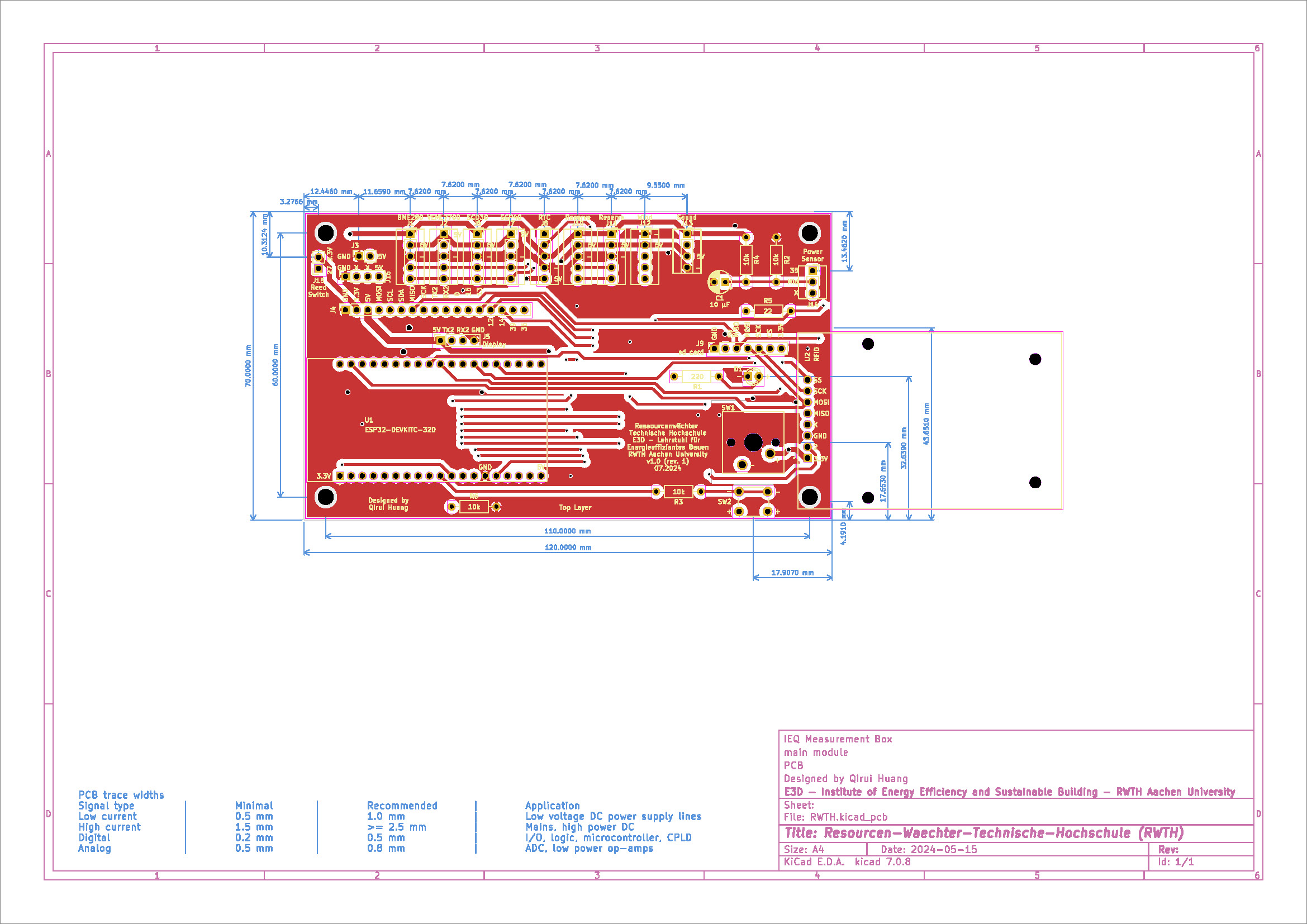
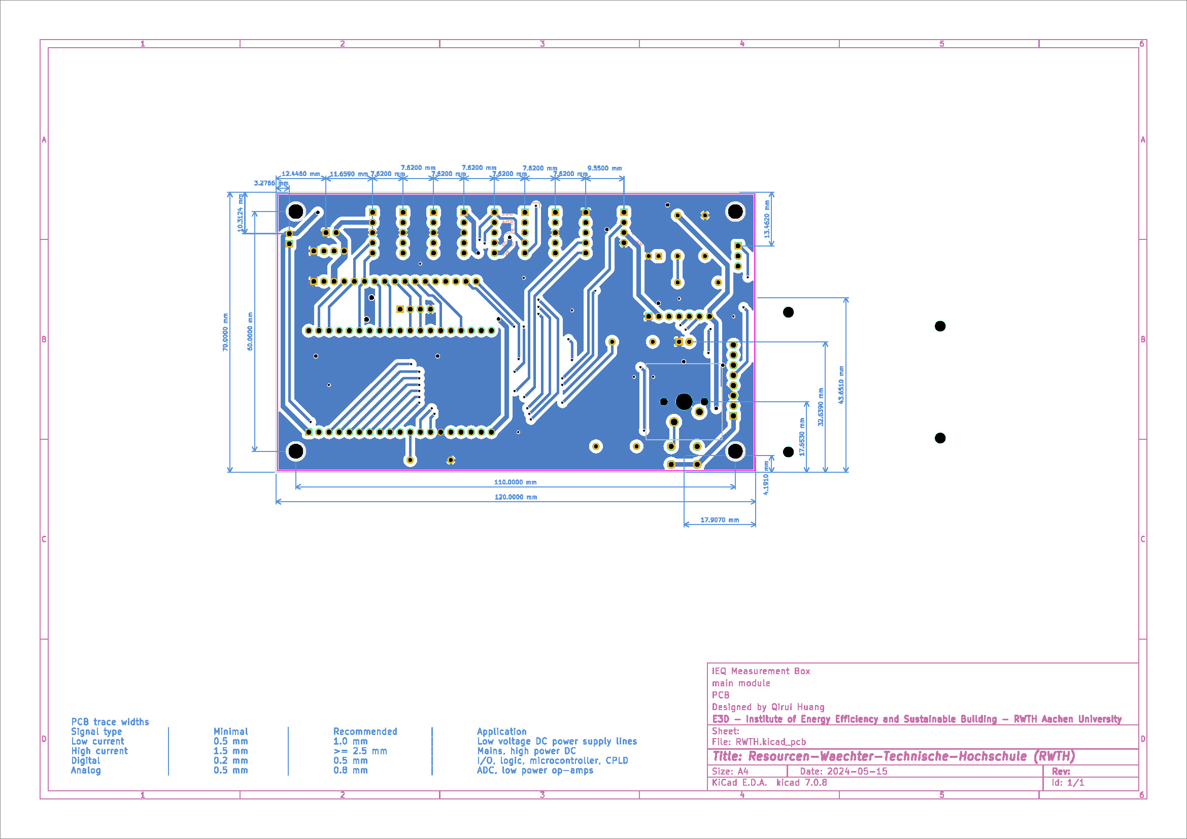
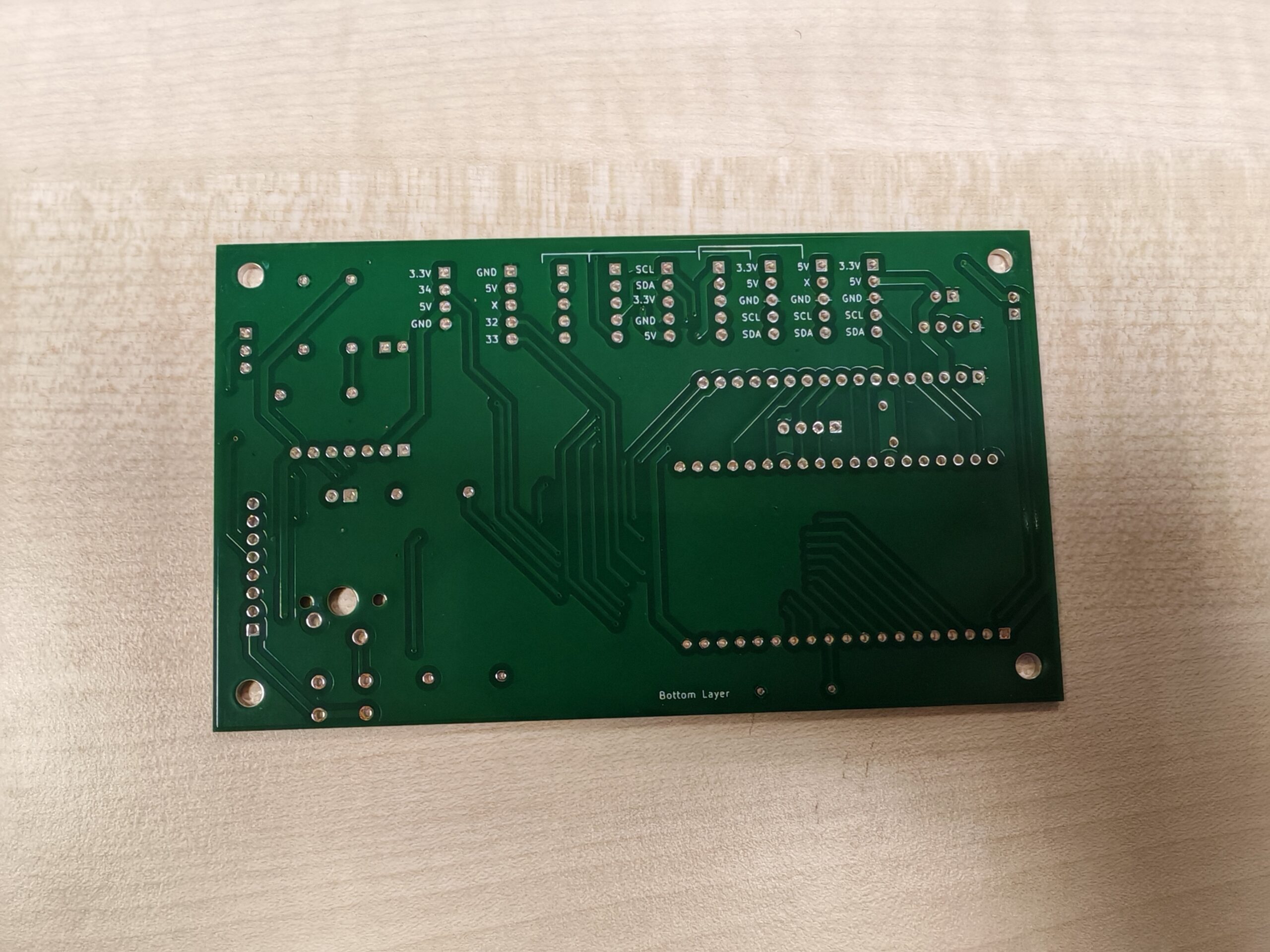
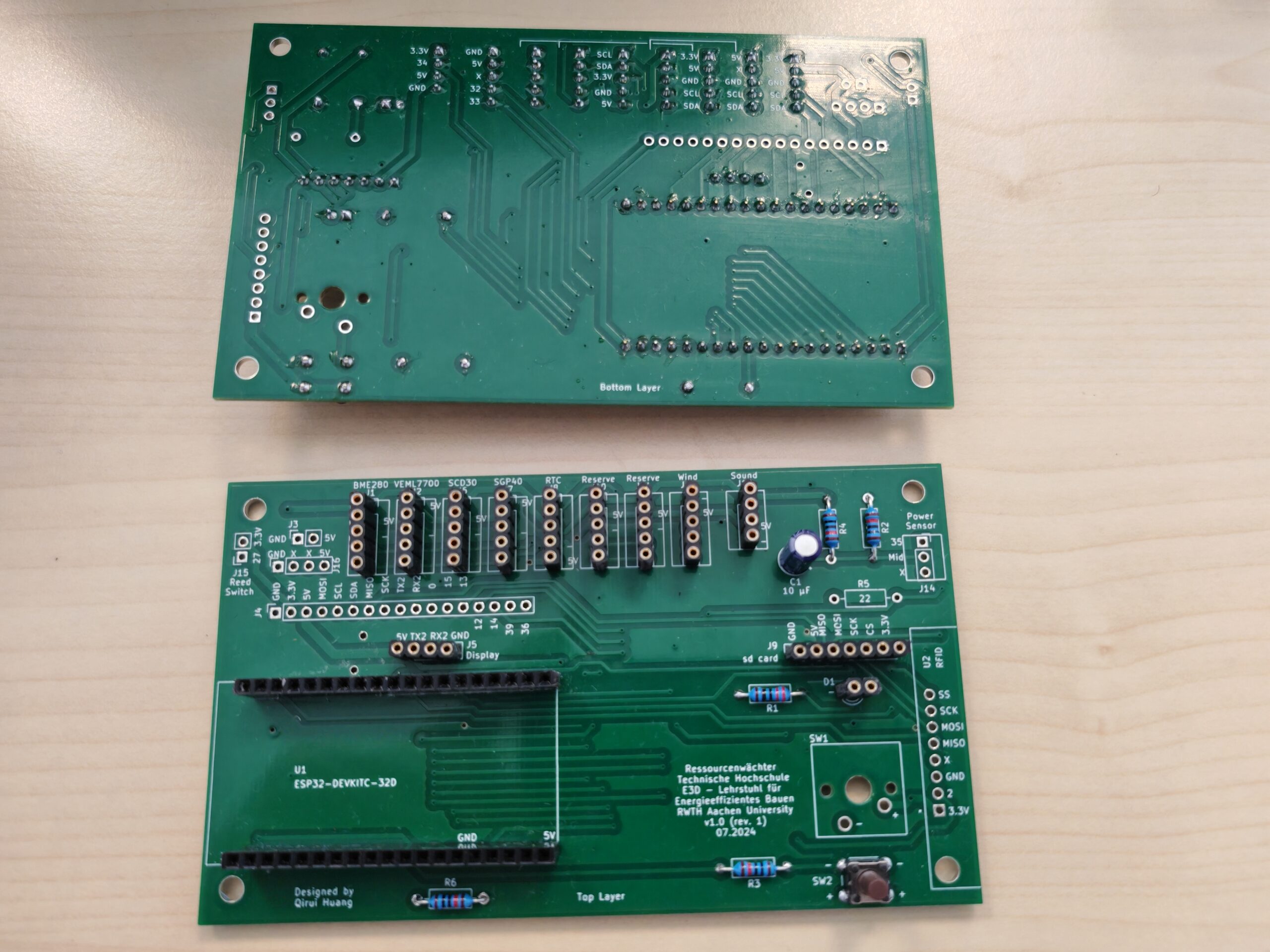
Because there are no complex circuits and to reduce costs, we have chosen simple double-layer PCB, and the schematics for the top and bottom layers are shown below:
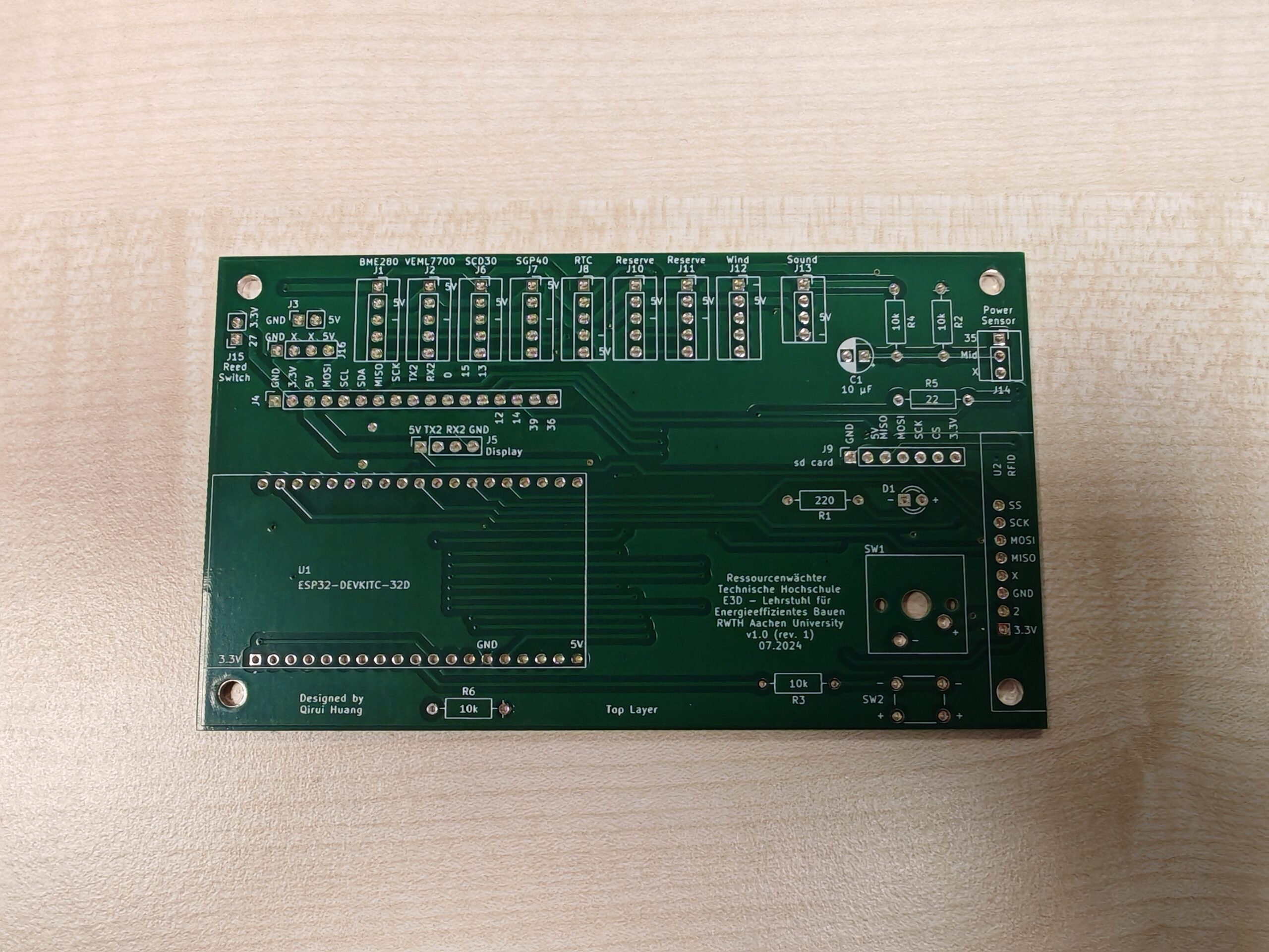
Solder the following components to each PCB:
- Pin socket (spacing 2.54 mm / height <= 8.5 mm)
- 1x 22 ohm resistor
- 1x 220 ohm resistor
- 4x 10k ohm resistor
- 1x 10 uF electrolytic capacitor (radial, 100 V)
- 1x button (6 x 6 x 9.5 mm or higher) (SW2), or keyboard switch (SW1)
We purchased two types of pin socket: a) spacing 2.54 mm & height 8.5 mm for the microcontroller and b) the more expensive one with spacing 2.54 mm & height 7.0 mm for the sensor interface (for a more secure jumper connection). The soldered PCB is shown in the figure below:
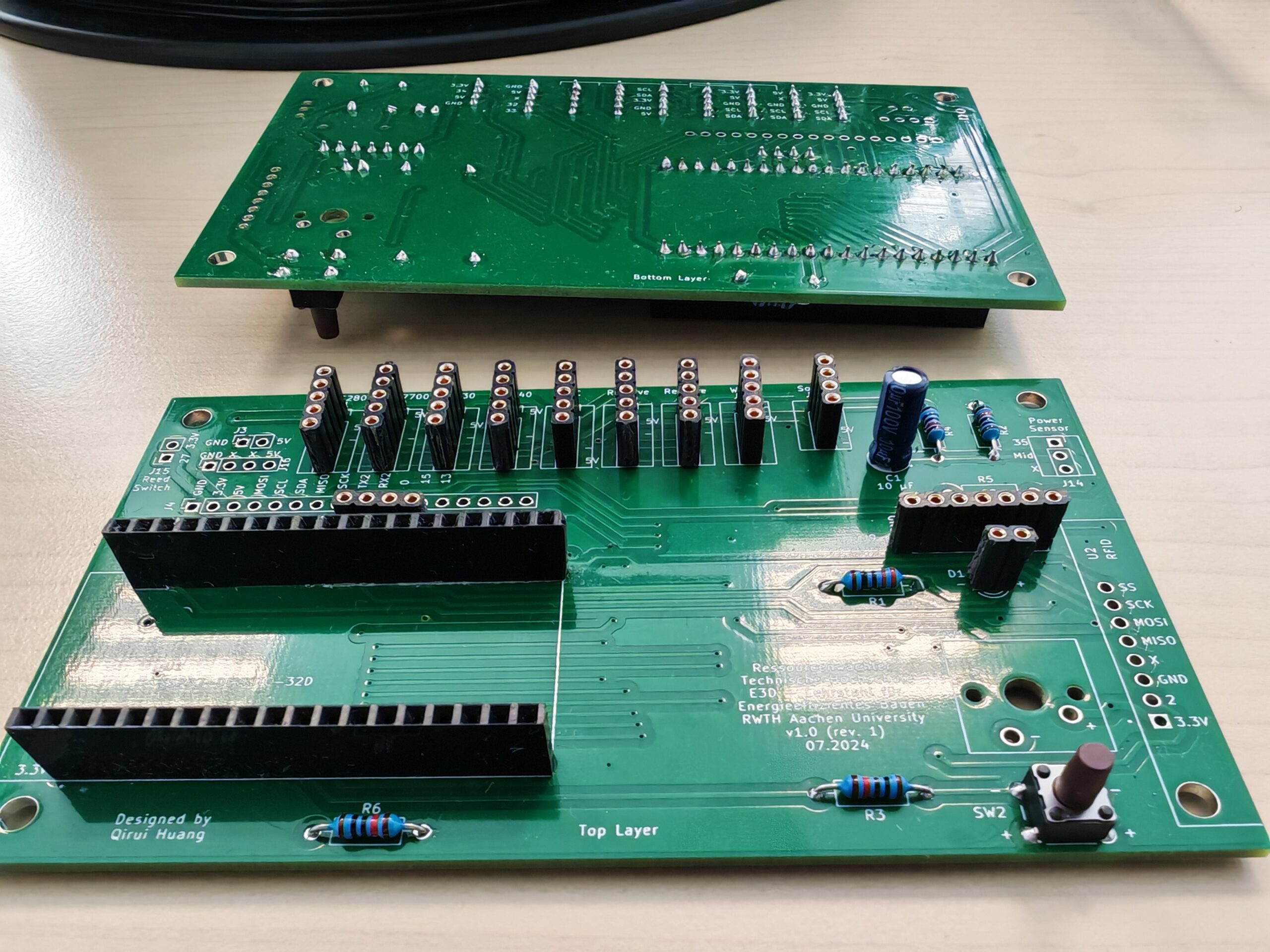
The reserved interfaces, such as RFID and window sensor interfaces, and the 22 ohm resistor for power sensor are not soldered in the above pictures and can be adjusted according to actual needs. Important: The 22 ohm resistor is designed for the power sensor SCT-013-000 (0-100A) with ESP32 (3.3V), if you’re using other modules of SCT-013, you need to calculate the ohm value needed, see the tutorial of OpenEnergyMonitor.
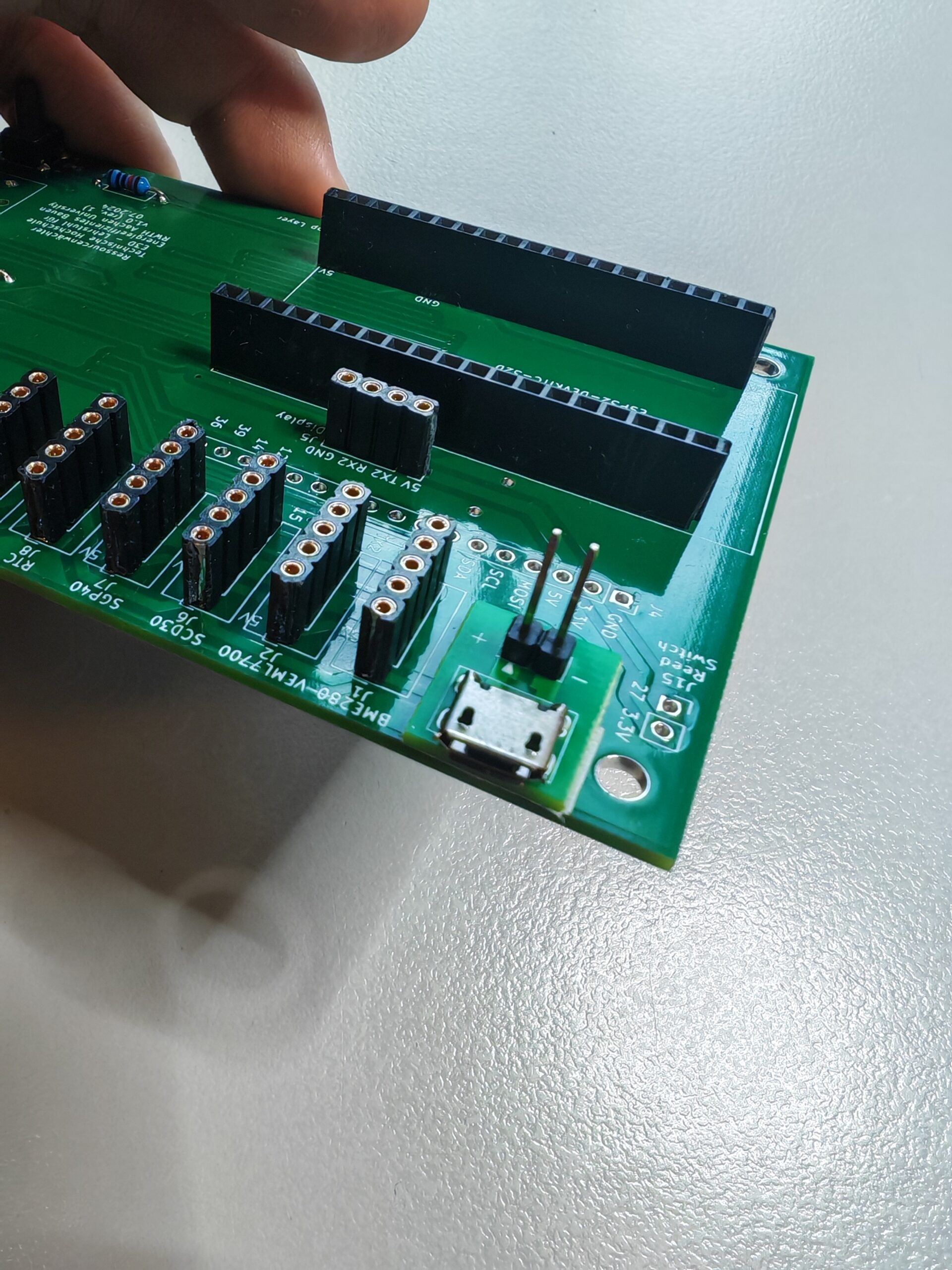
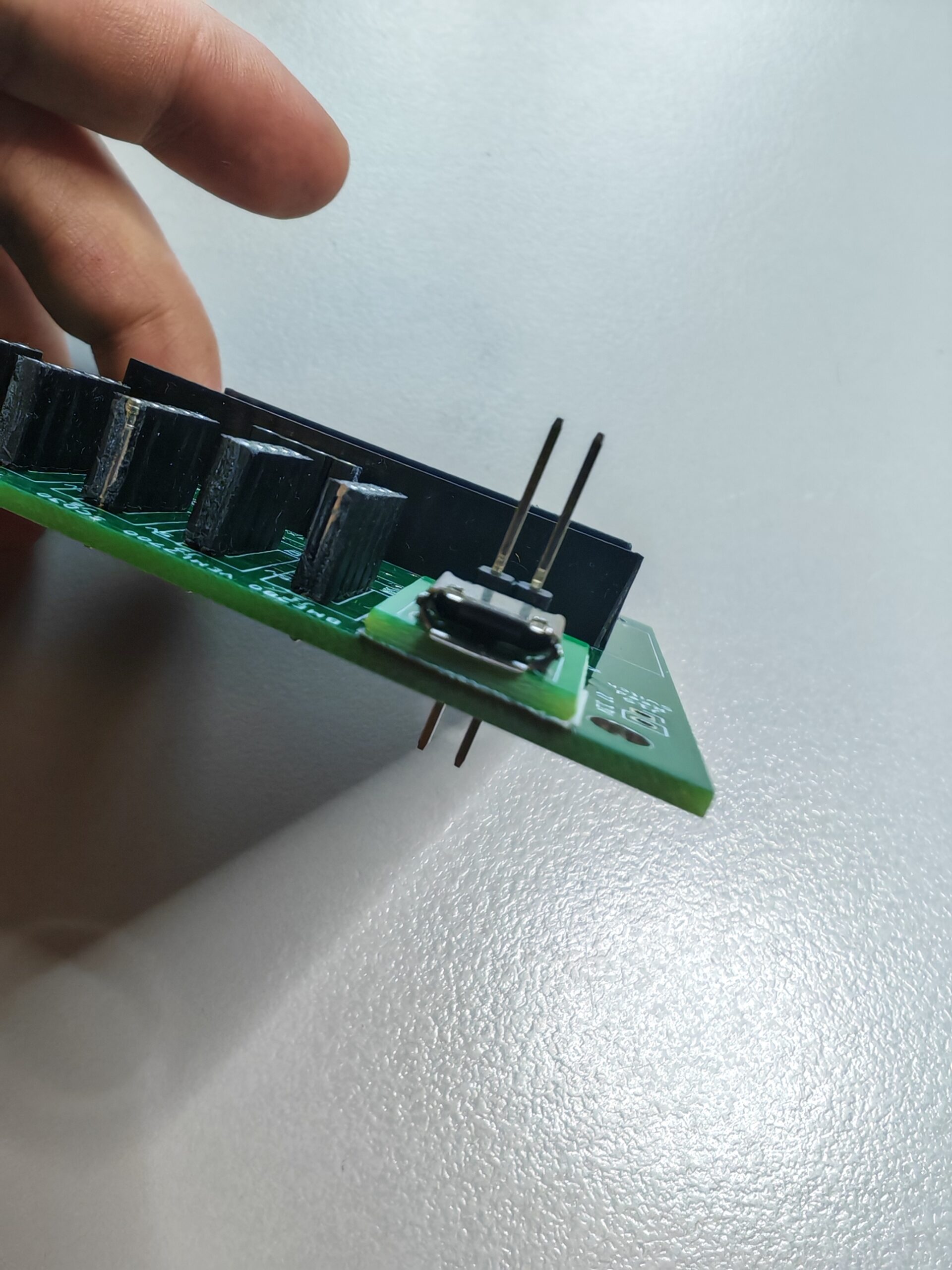
Next, solder the power interface module to the PCB. Because the Nextion display comes with a Micro-USB power interface module, we did not design a separate power interface directly on the PCB. Although the solder mask on the PCB ensures that there is no electrical connection between the exposed solder pads on the back of the power supply interface module and the PCB, we still recommend sticking a layer of insulating tape on the back of the module for safety.
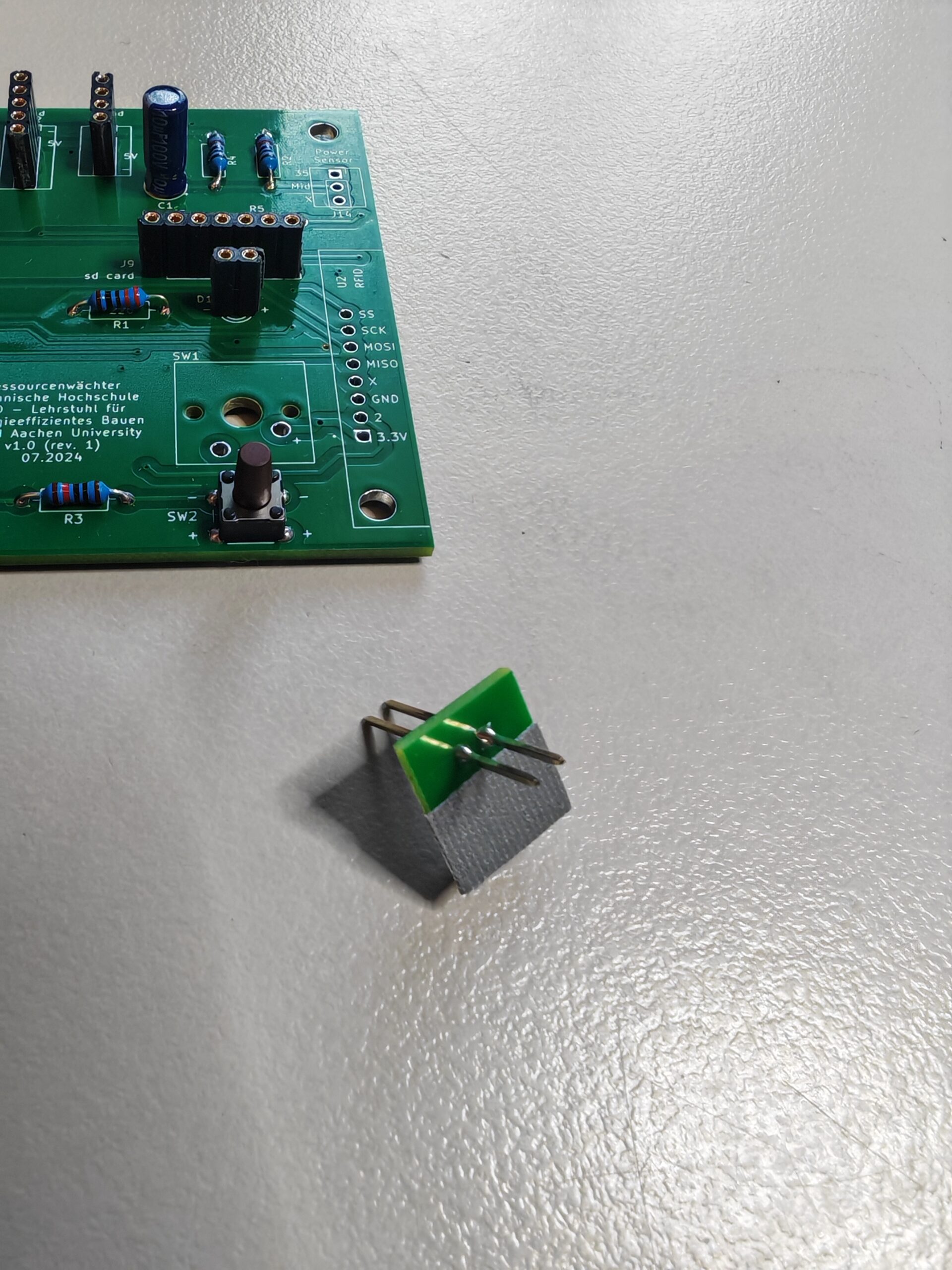
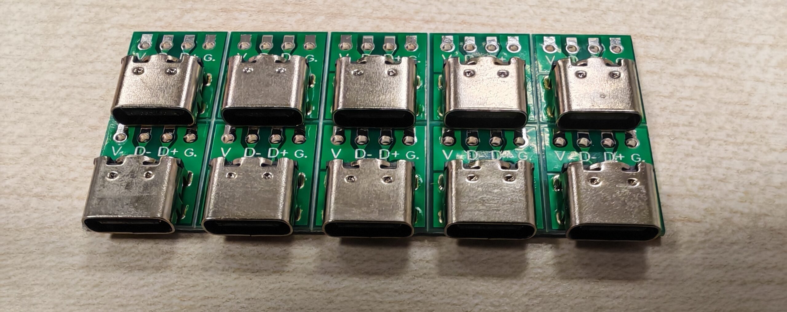
You can also purchase other types such as a 4-pin USB Type C module for power supply separately (J16 instead of J3), for example:
After completing the above steps, you can start assembling the Ressourcenwächter.