Assembling Ressourcenwächter
Select the appropriate sensors according to the Sensor Configurations based on your measurement requirements. The following assembly instructions include the following sensors:
- Sensirion SCD30 for CO2
- Sensirion SGP40 for VOC
- Bosch BME280 (4pins, 5V version) for air temperature / humidity / air pressure
- Vishay/Adafruit VEML7700 for illuminance
- DFROBOT SEN0232 Gravity Analog Sound Level Meter for sound level in dB(A)
- Modern Device Wind Sensor Rev. C
In addition, the following required components are included:
- Microcontroller Espressif ESP-32 DevKitC (WROOM-32D/E)
- RTC module DS3231
- SD card module DEBO MICROSD2 with 8 GB Intenso SDHC card
- For supported SD card types, see Formatting the SD card.
- 5.0″ Nextion Intelligent HMI Display 5″ NX8048P050-011R (resistive, resolution 800×480)
- The capacitive version NX8048P050-011C is also compatible, but more expensive.
- It is also possible to do without the display and use Ressourcenwächter as a non-interactive measuring device.
- In some countries and regions, you can find an alternative to Nextion NX8048P050-011R/C: Taojingchi TJC8048X550_011R/C. They seem to be the OEM’s own brand and are much cheaper. The TJC screens use very similar development software (USART HMI) compared to Nextion Editor, and we also provide corresponding GUI code for it, see
./software/gui/TJC_USART_HMI
- Jumper wires (male to female)
If you are using our enclosure design and have prepared the enclosure according to our instructions, you will need the following parts to fix the PCB, sensors, and enclosure:
- 4x oval-head screws, M3 x 8mm,
- 4x flat countersunk head screws, M3 x 10mm,
- 12x hexagon nuts, M3,
- Depending on your sensor selection, multiple oval-head screws (M2 x 6~8mm) and hexagon nuts (M2) to fix the sensor to the enclosure.
The components used in this guide are shown in the figure below.

1. Install LED indicator
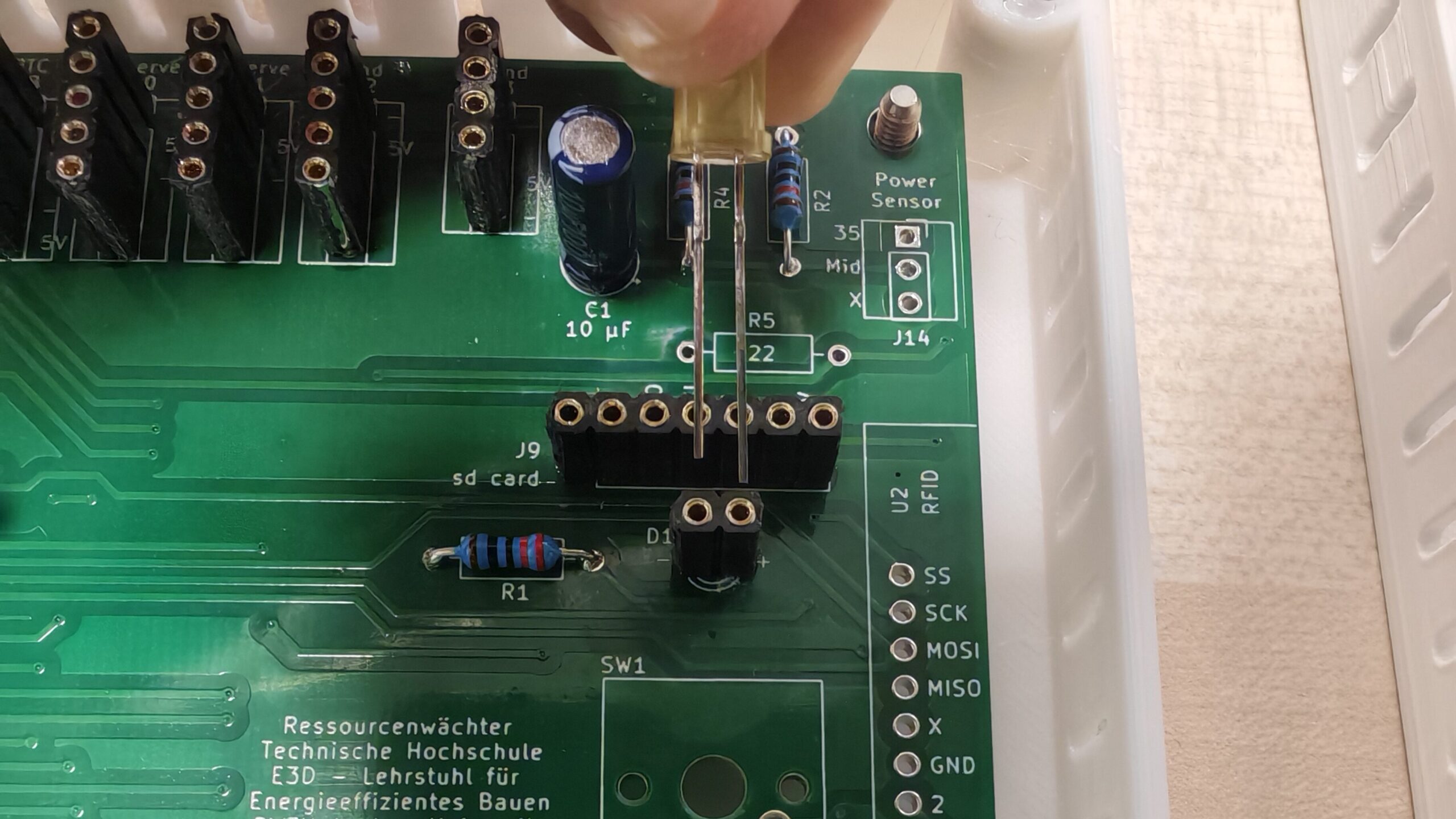
Choose your preferred LED color and size. Trim the pins to fit the pin socket.
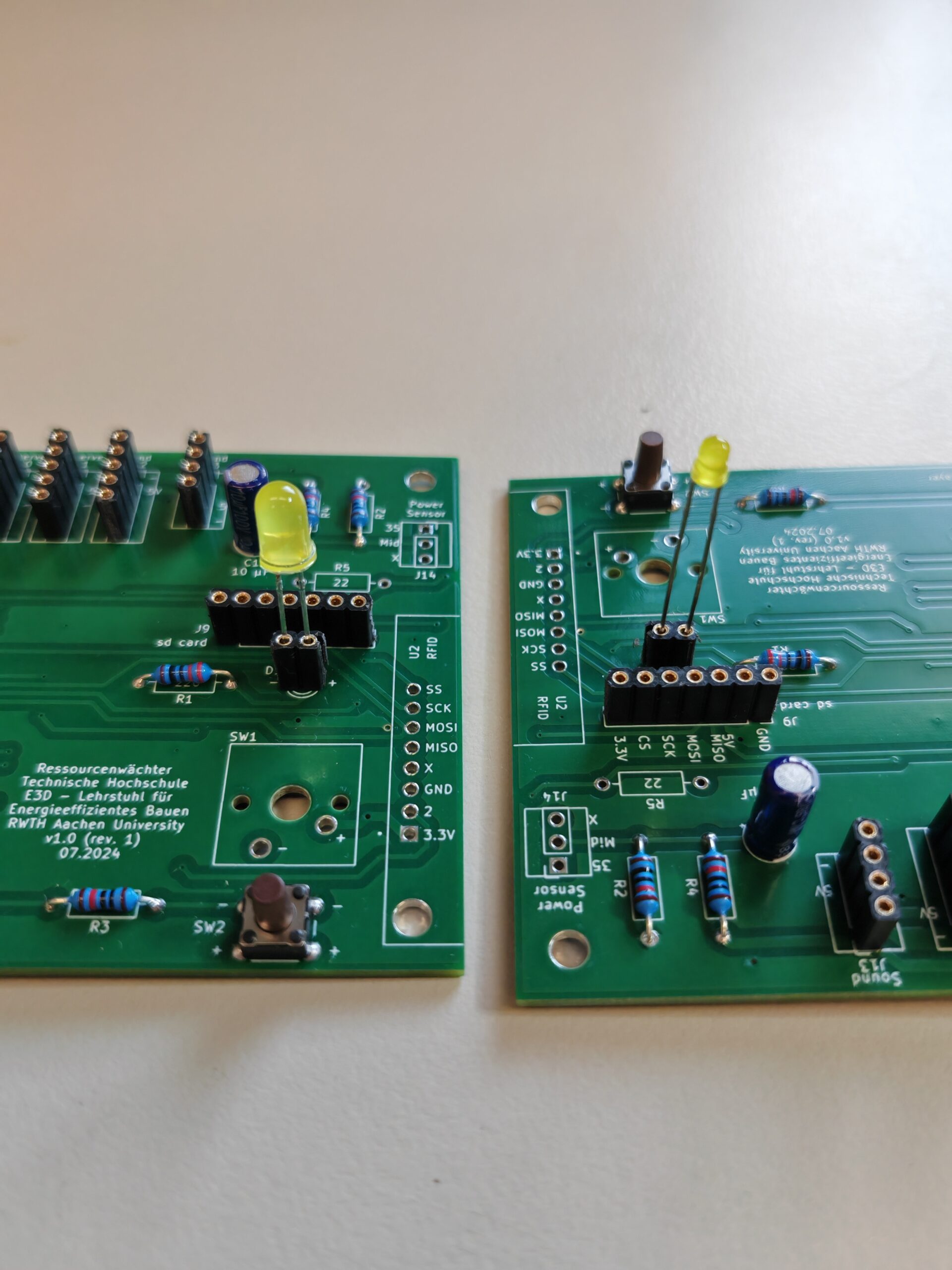
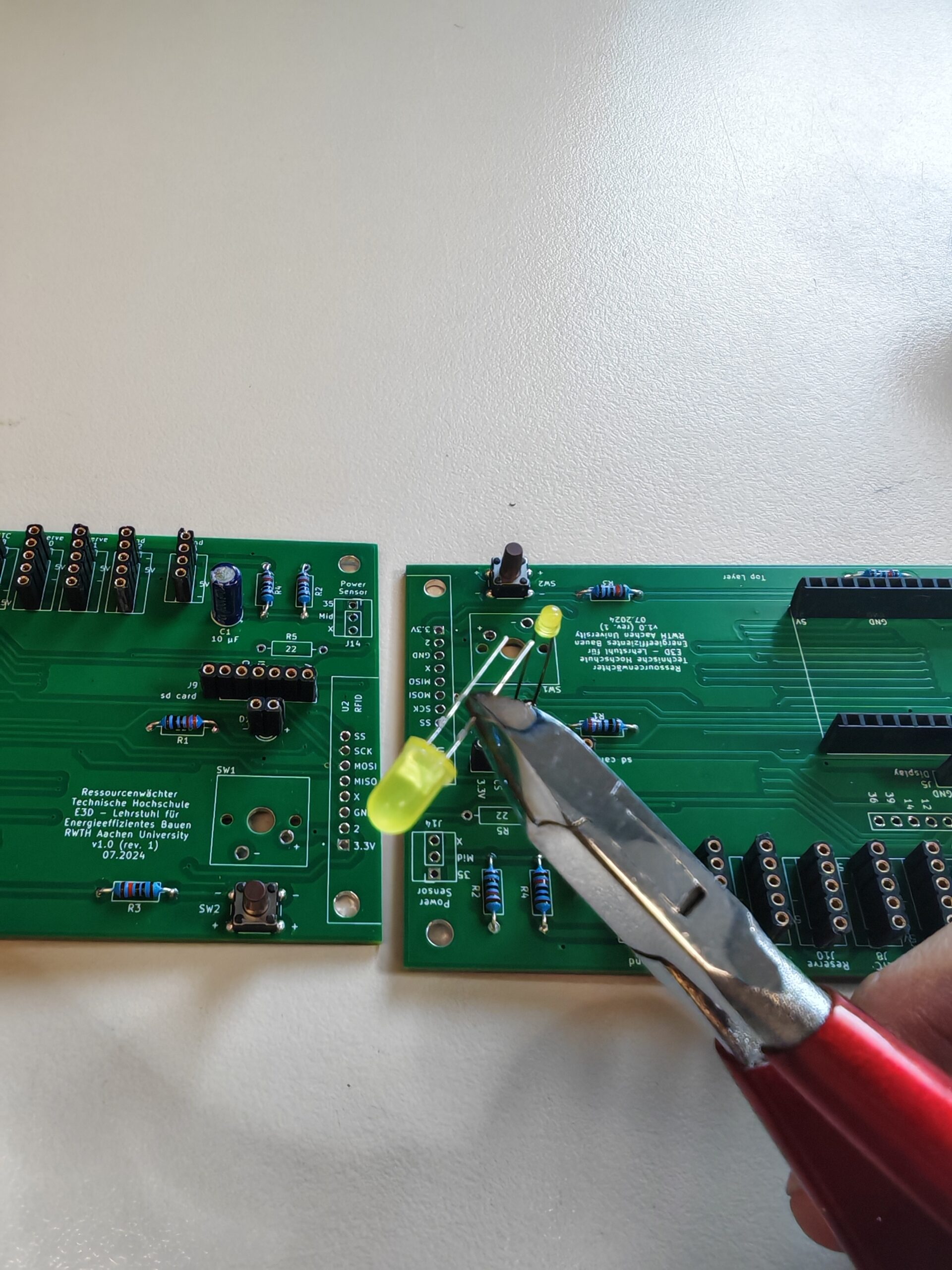

When installing, pay attention to the positive and negative pins. You can also solder the LED directly onto the PCB instead of using the pin socket.
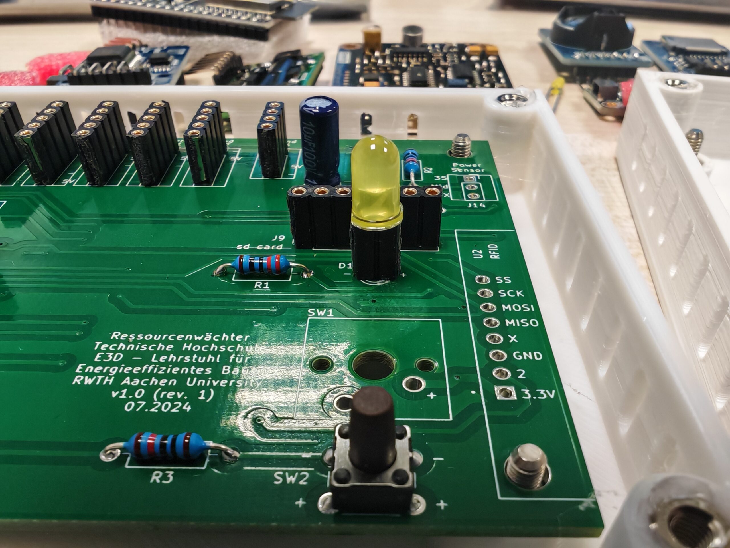
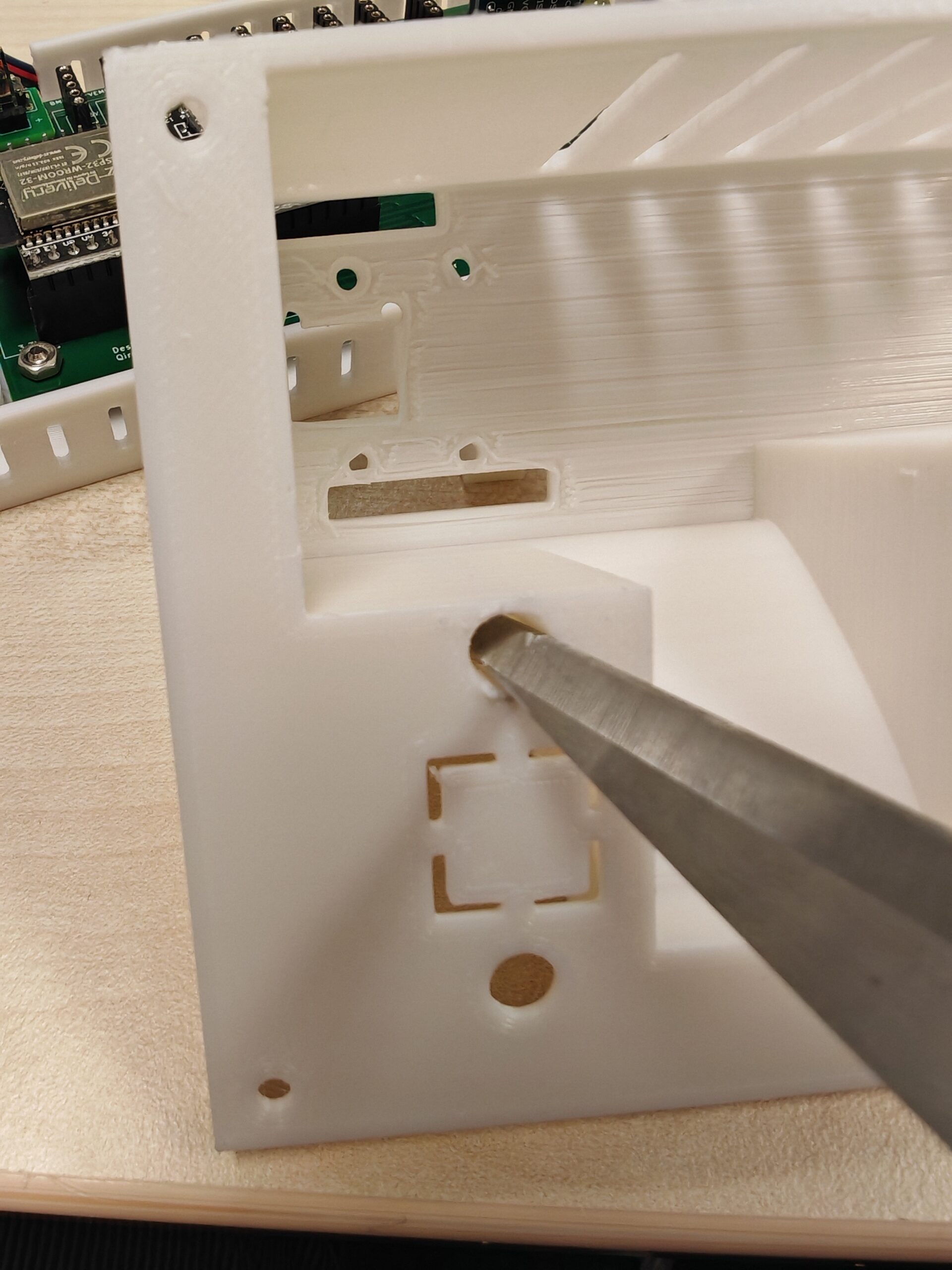
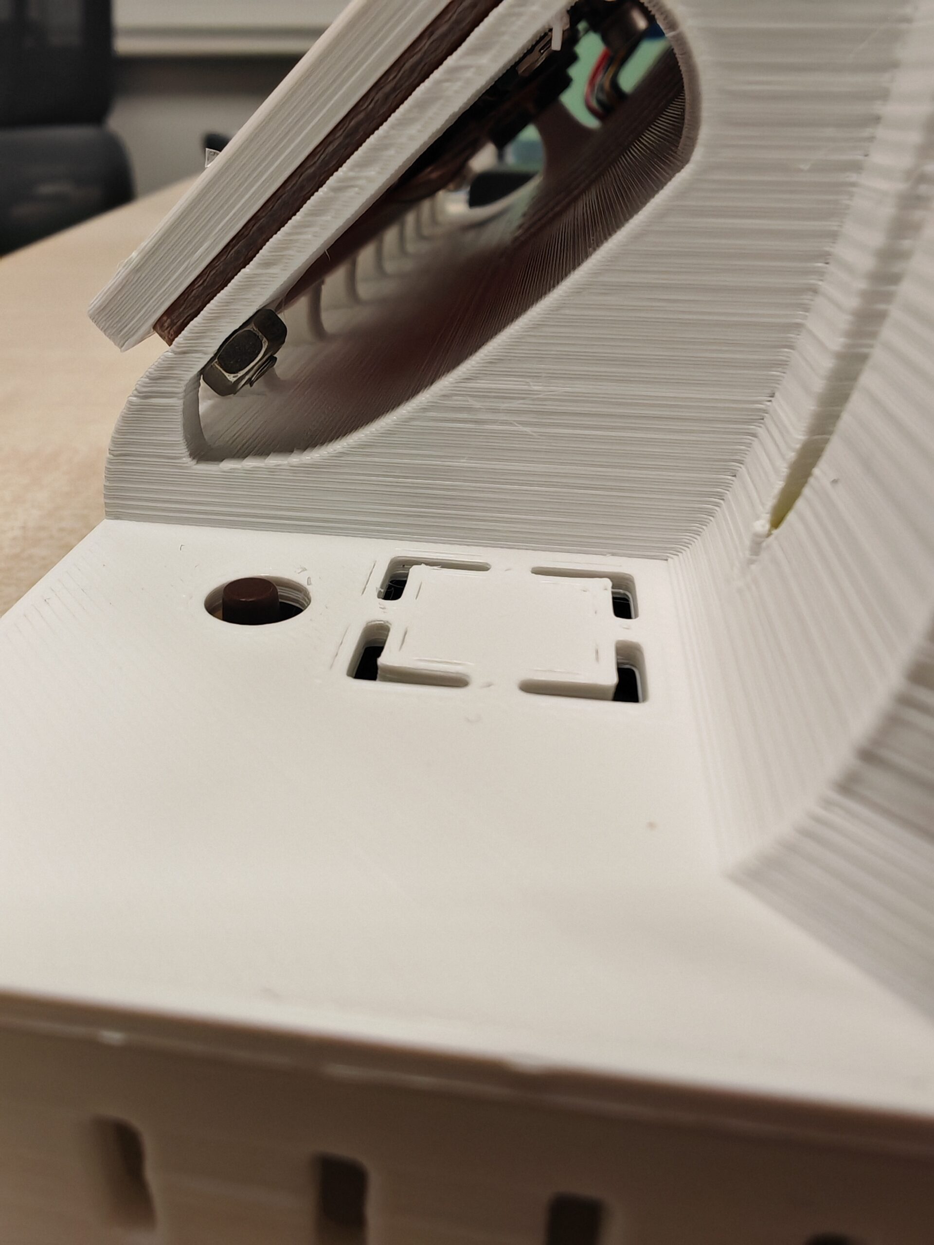
If you use a larger LED with a pin socket (also depends on the height of the pin socket), as shown on the left in the picture below, you may need scissors or other tools to enlarge the LED hole in the enclosure appropriately. If you have chosen a keyboard switch (SW1) instead of the button (SW2) in the picture below, use a tool to open the corresponding rectangular opening in the enclosure.
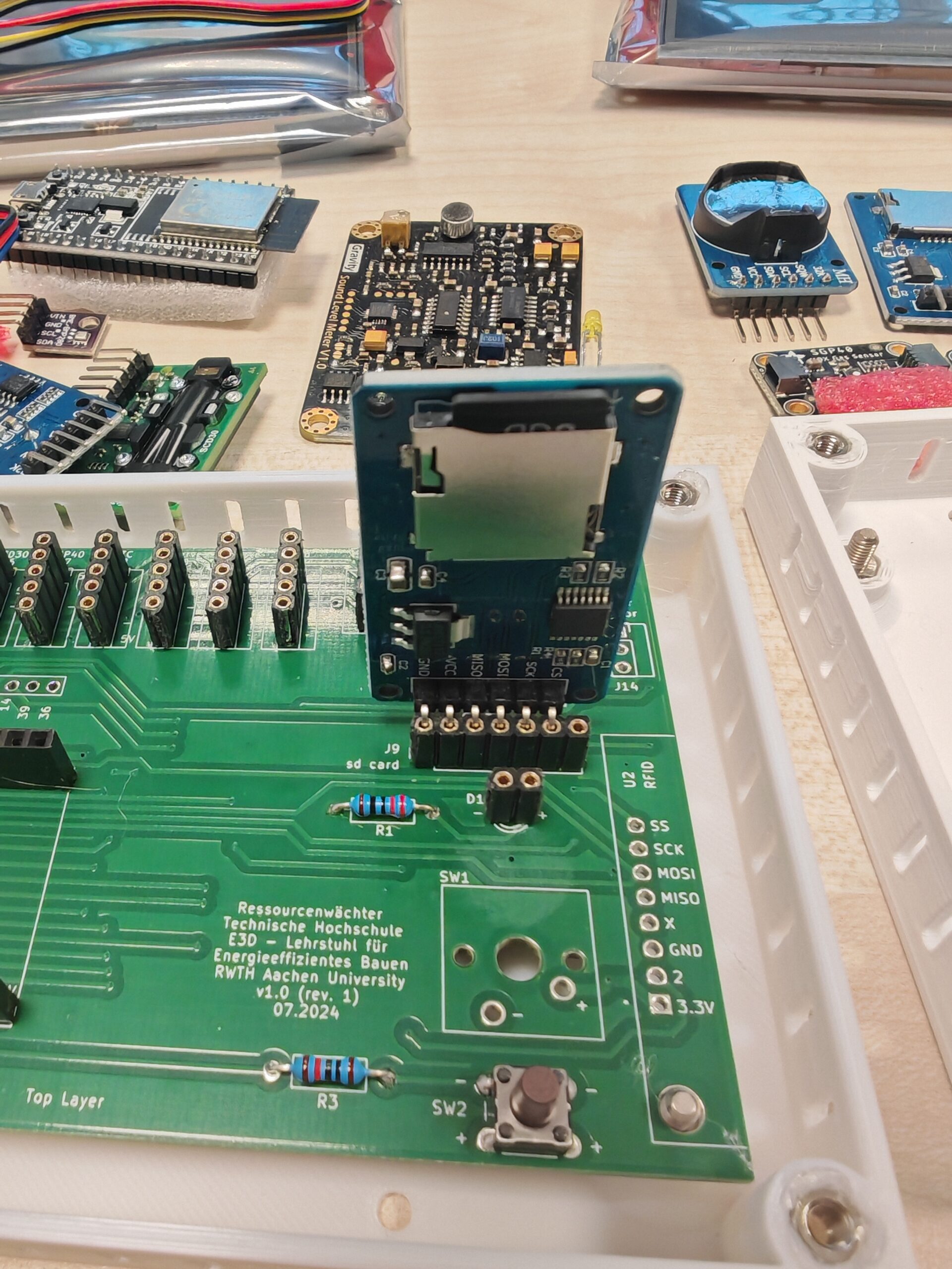
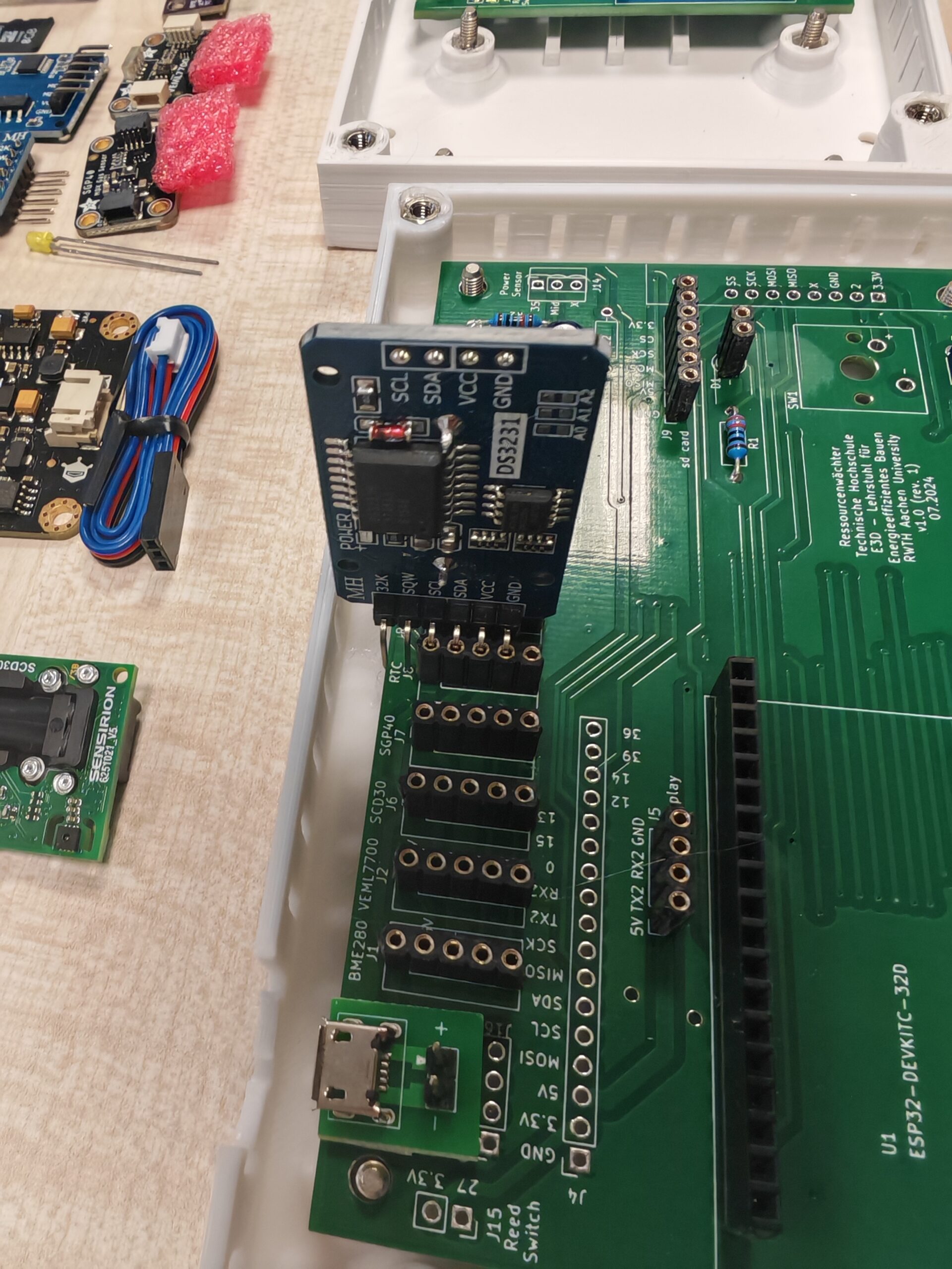
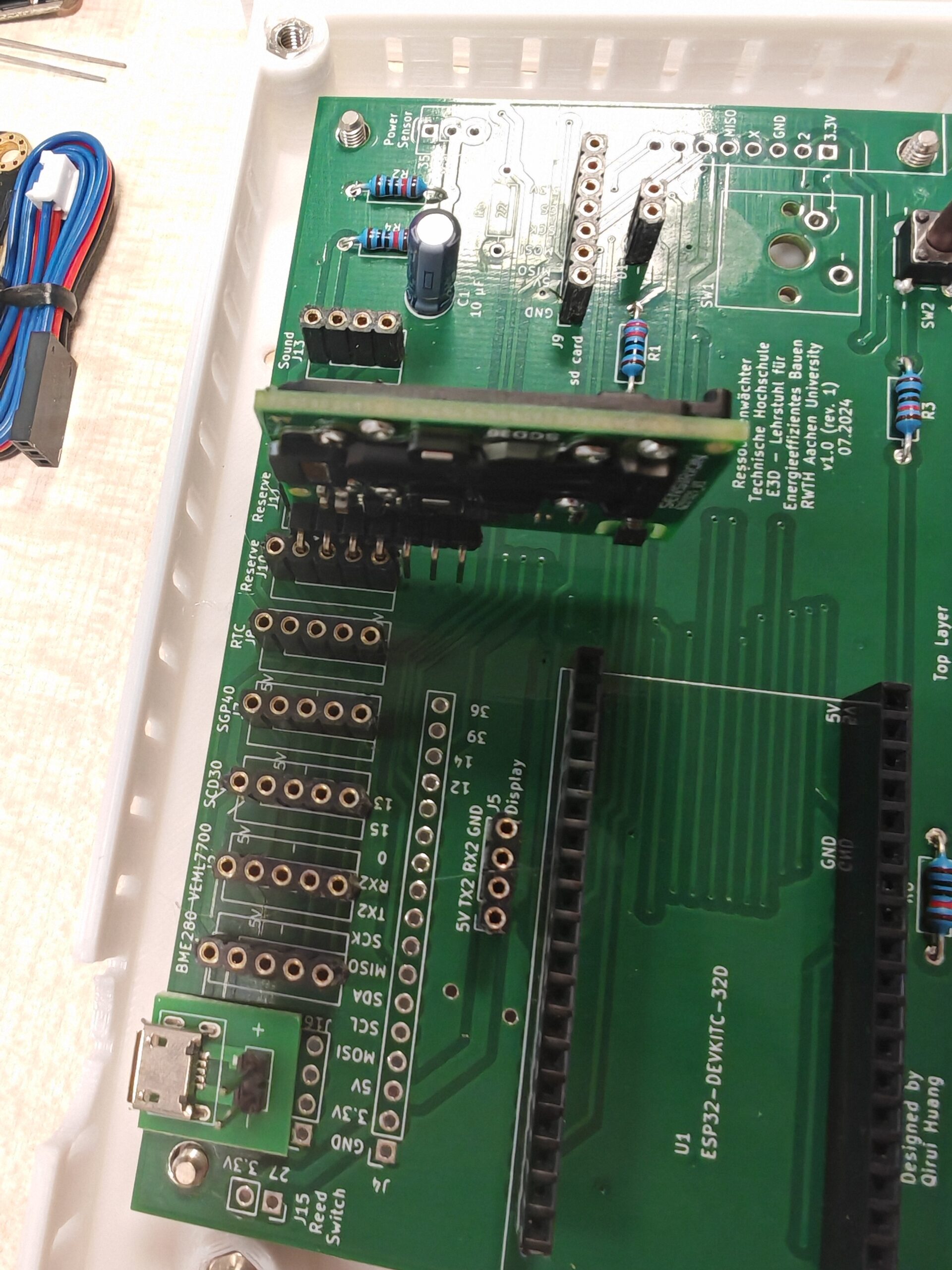
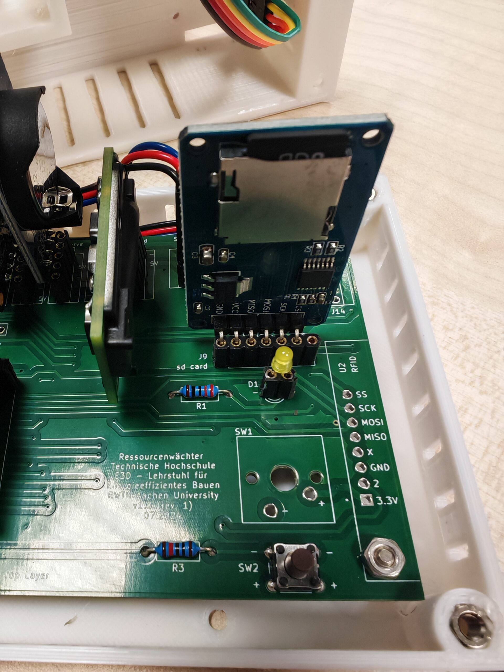
2. Install the SD card and RTC module
Insert the SD card and RTC modules into the pin socket according to the PCB footprints (figure below for reference). Note that the RTC module requires a separate power supply from a coin-cell battery. If the RTC module you purchased does not come with a battery, you need to purchase one separately.
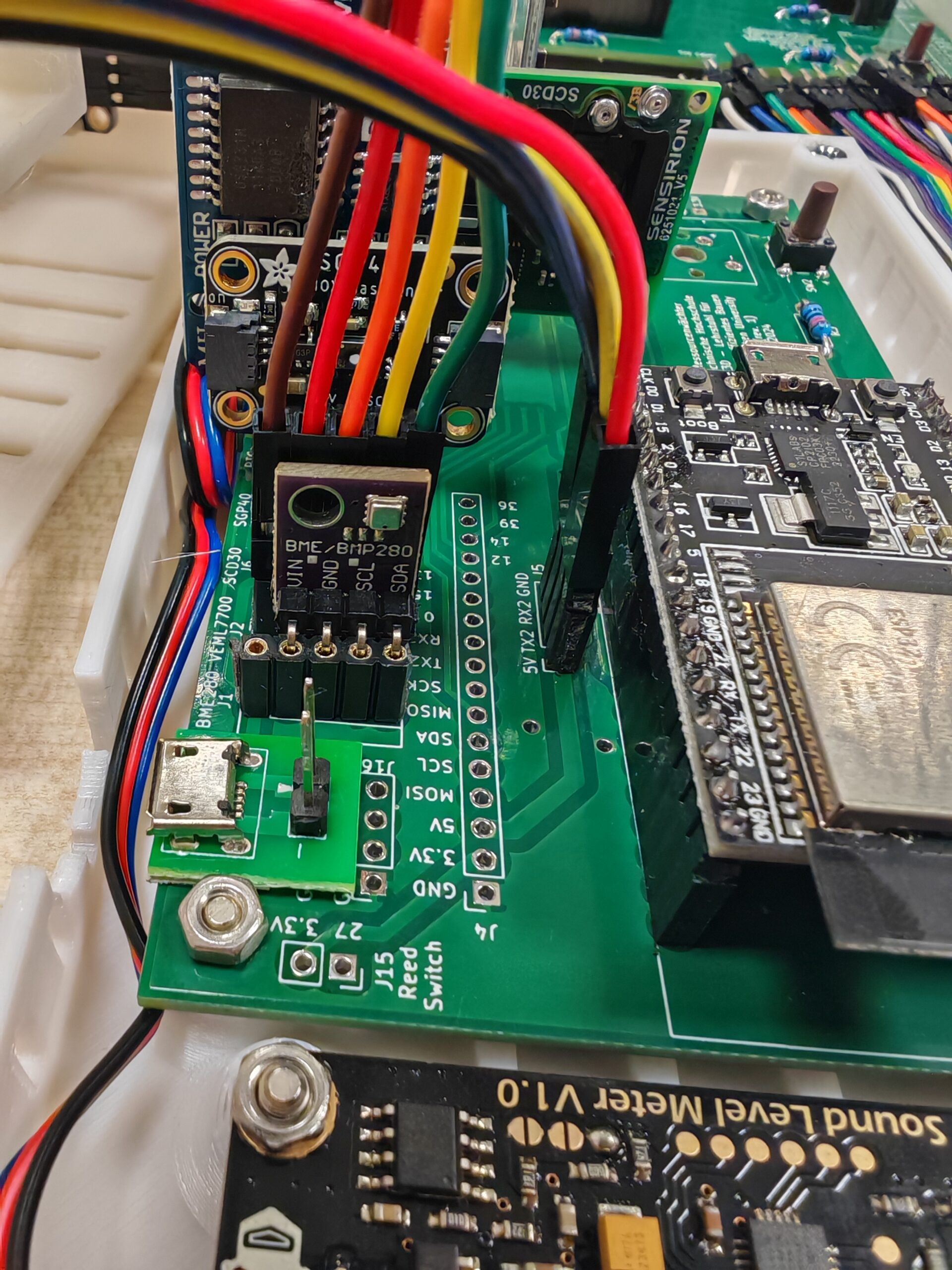
3. Install the microcontroller and sensors
Insert the sensors into the pin sockets according to the PCB footprints.
3.1 DFROBOT SEN0232 Gravity Analog Sound Level Meter
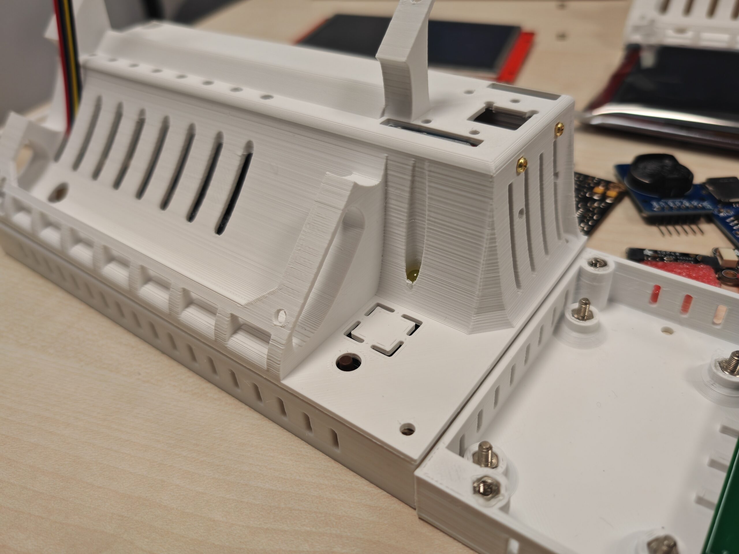
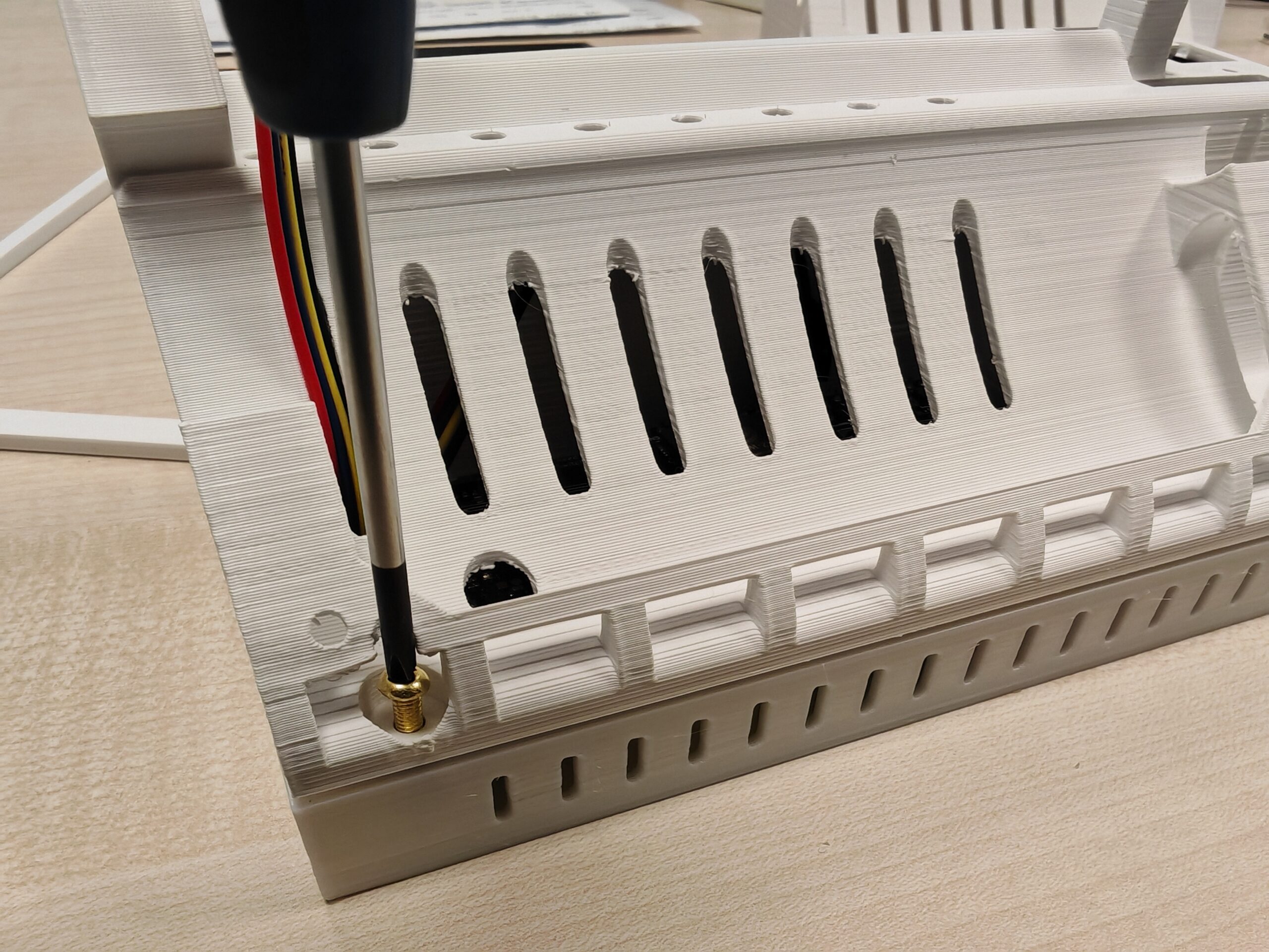
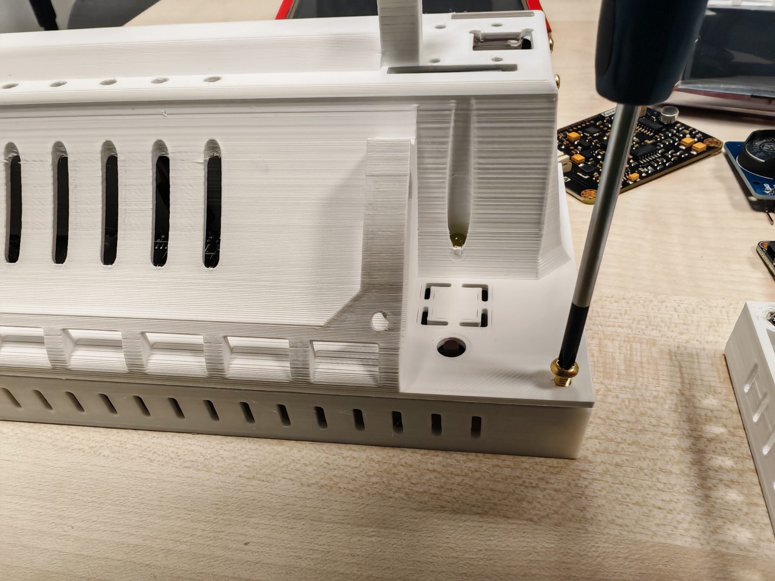
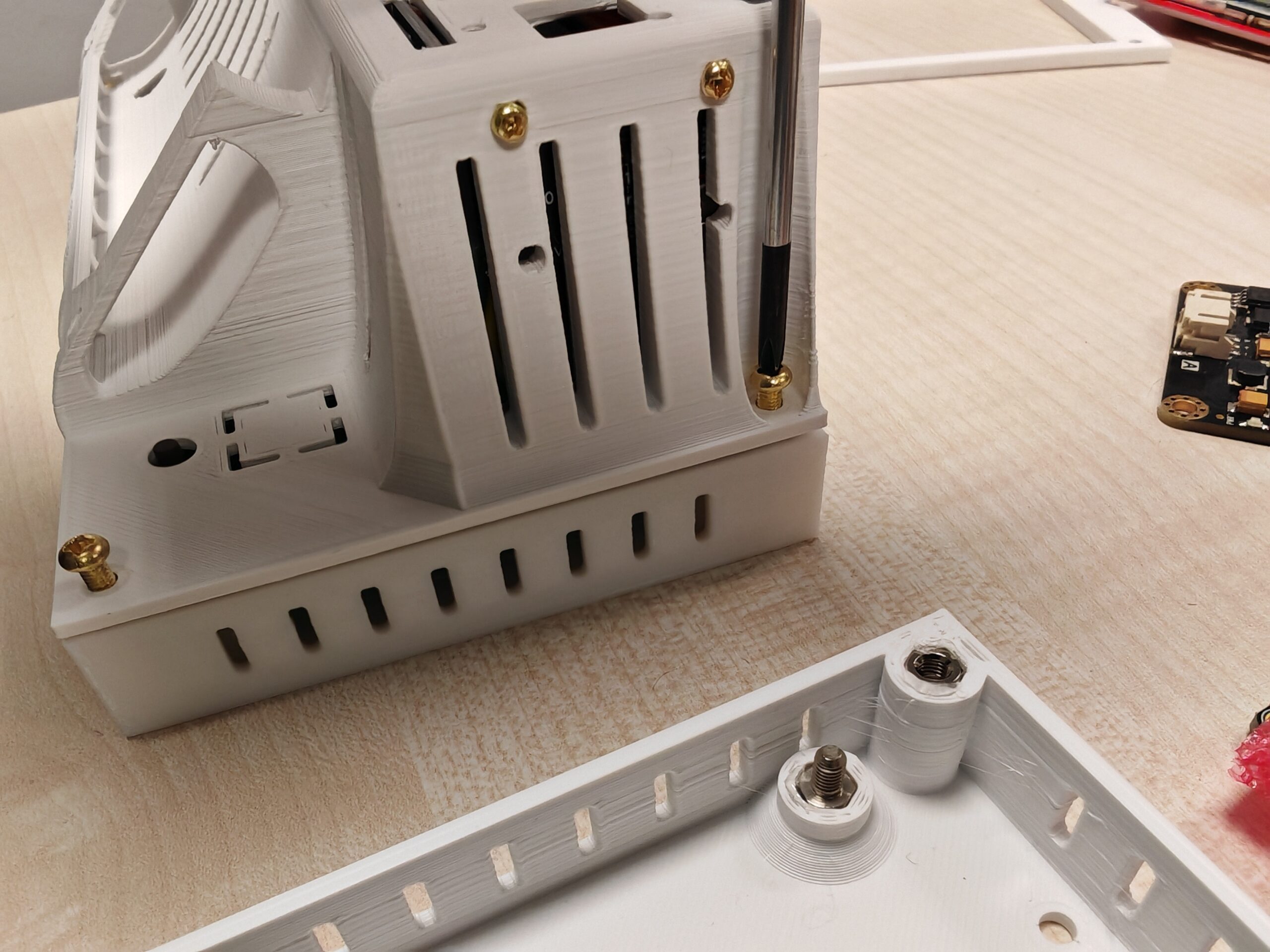
After installation, secure the SEN0232 and PCB to the housing base with the hexagon nuts.
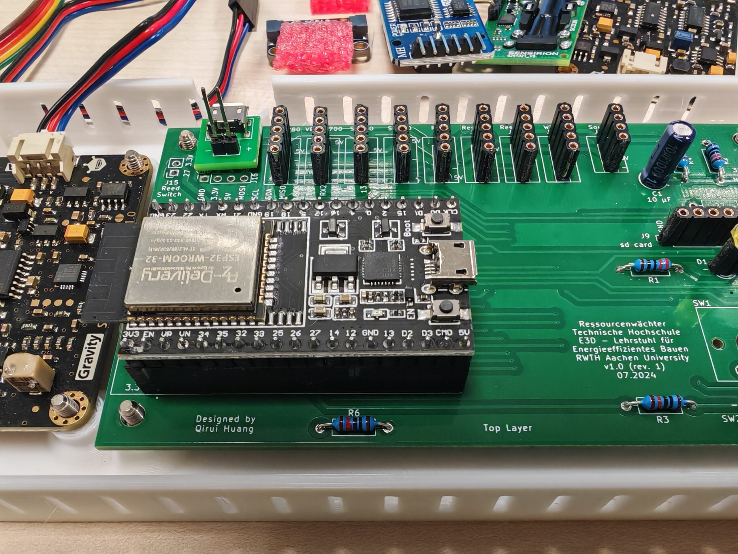
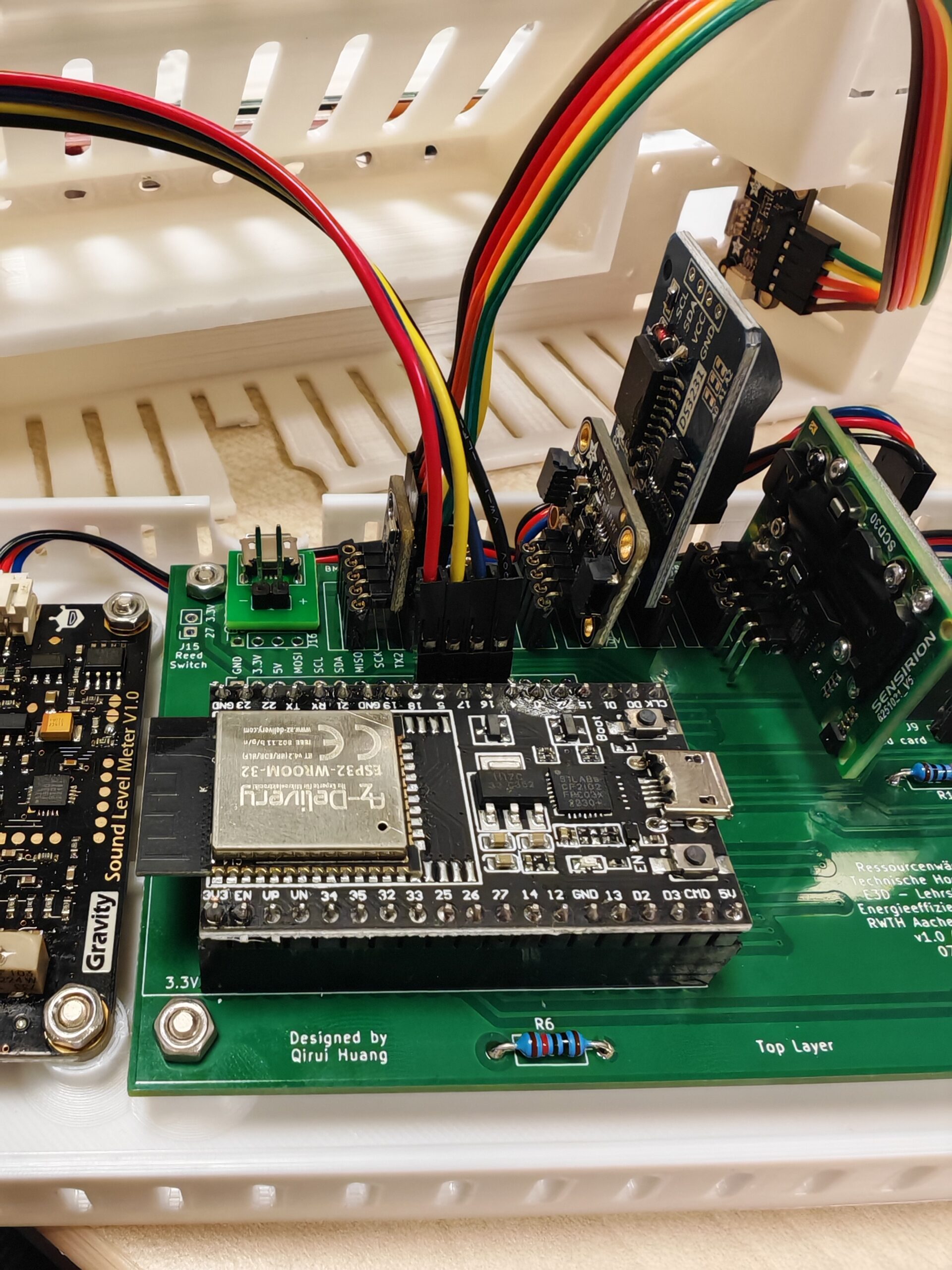
3.2 Microcontroller
Install the microcontroller as shown below.
3.3 BME280 & SGP40
The BME and SGP sensors can be plugged directly into the pin socket without jumper wires.
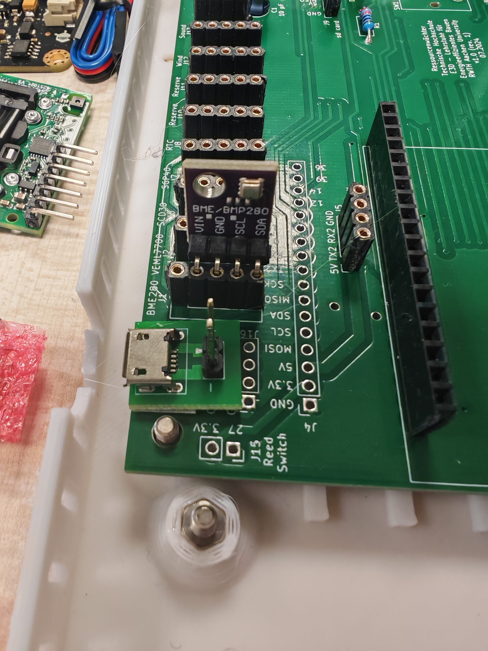

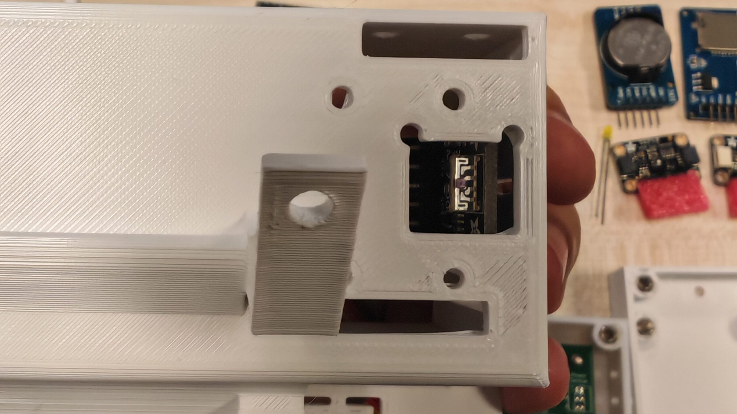
3.4 VEML 7700
The VEML7700 needs to be installed in the opening provided in the enclosure. When designing the enclosure, we have provided multiple fixing holes to make it as compatible as possible with different types of VEML7700.
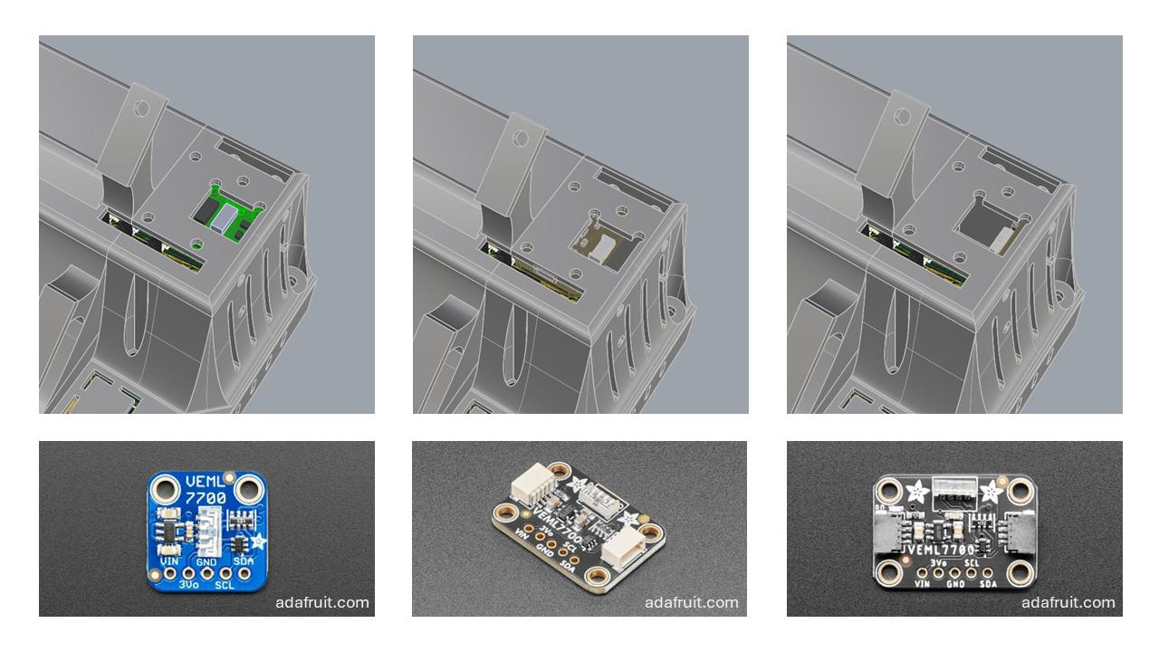
The following figure shows an example of installing the 90-degree angle version of Adafruit’s VEML7700 development board.
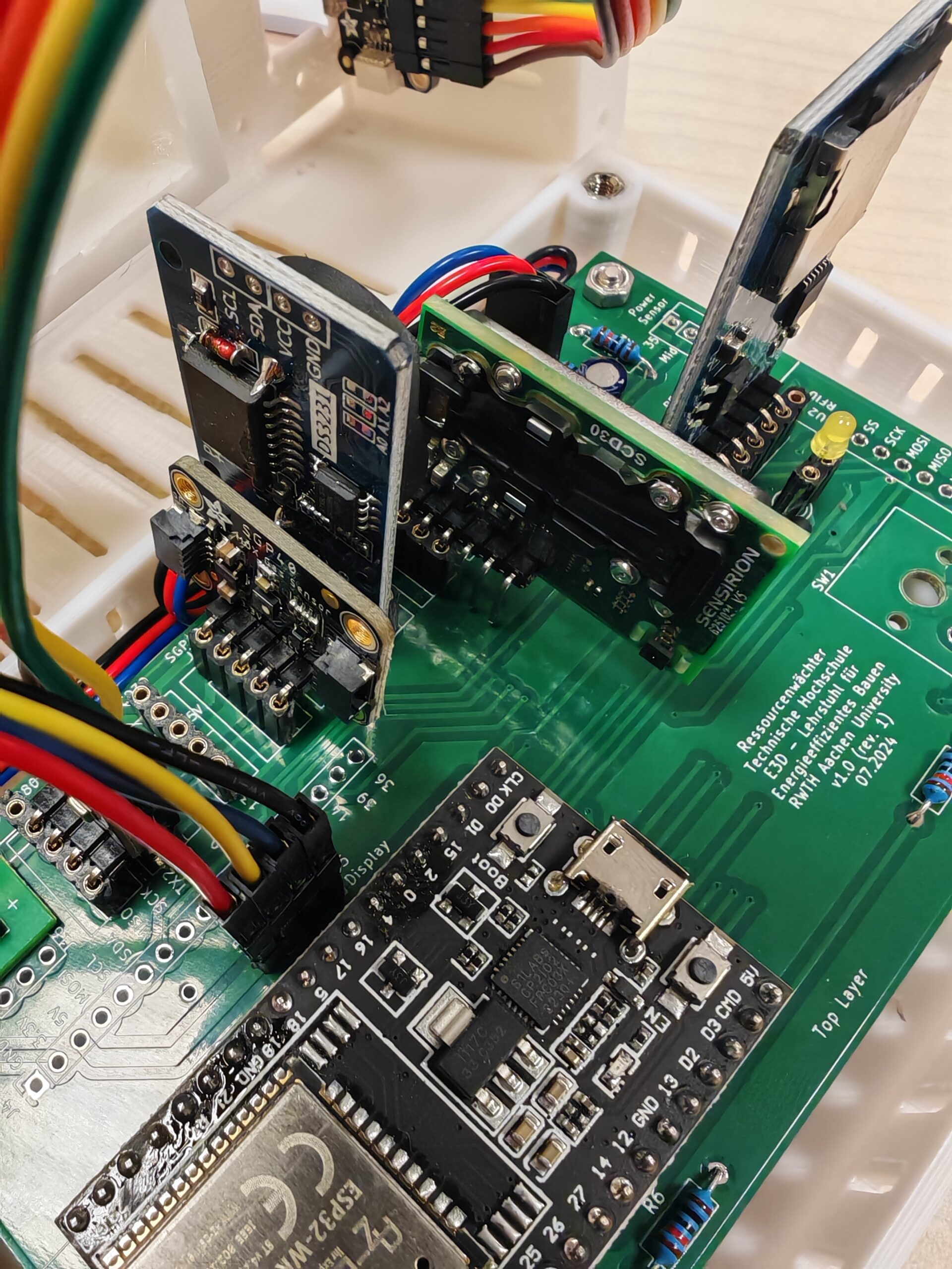
3.5 SCD30
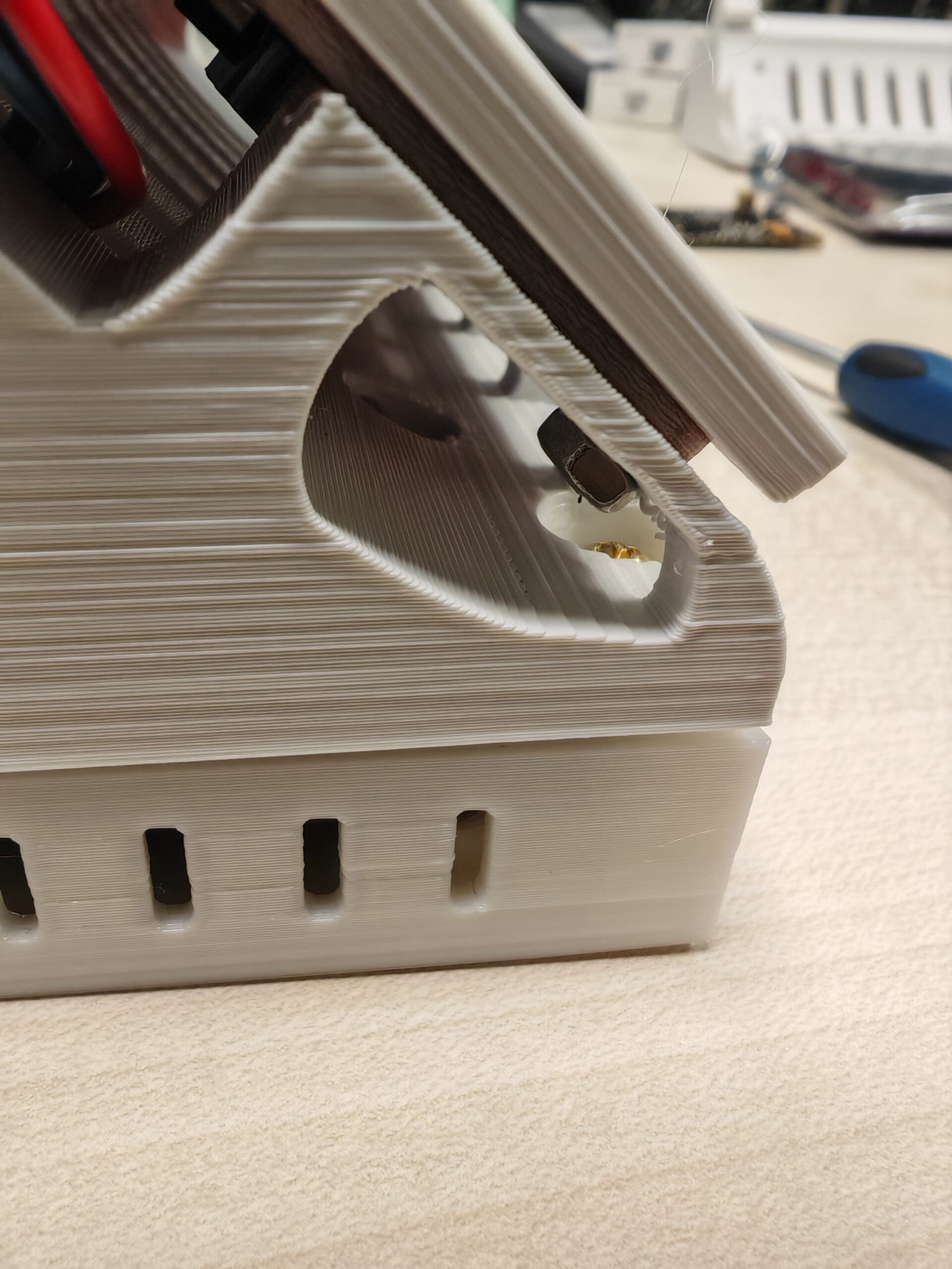
For the CO2 sensor SCD30, you can fix the sensor in the openings on the back of the enclosure according to the Sensirion guidelines and use jumper wires or plug it directly into the I2C pin socket on the PCB (Reserve J10 or J11, as shown below).
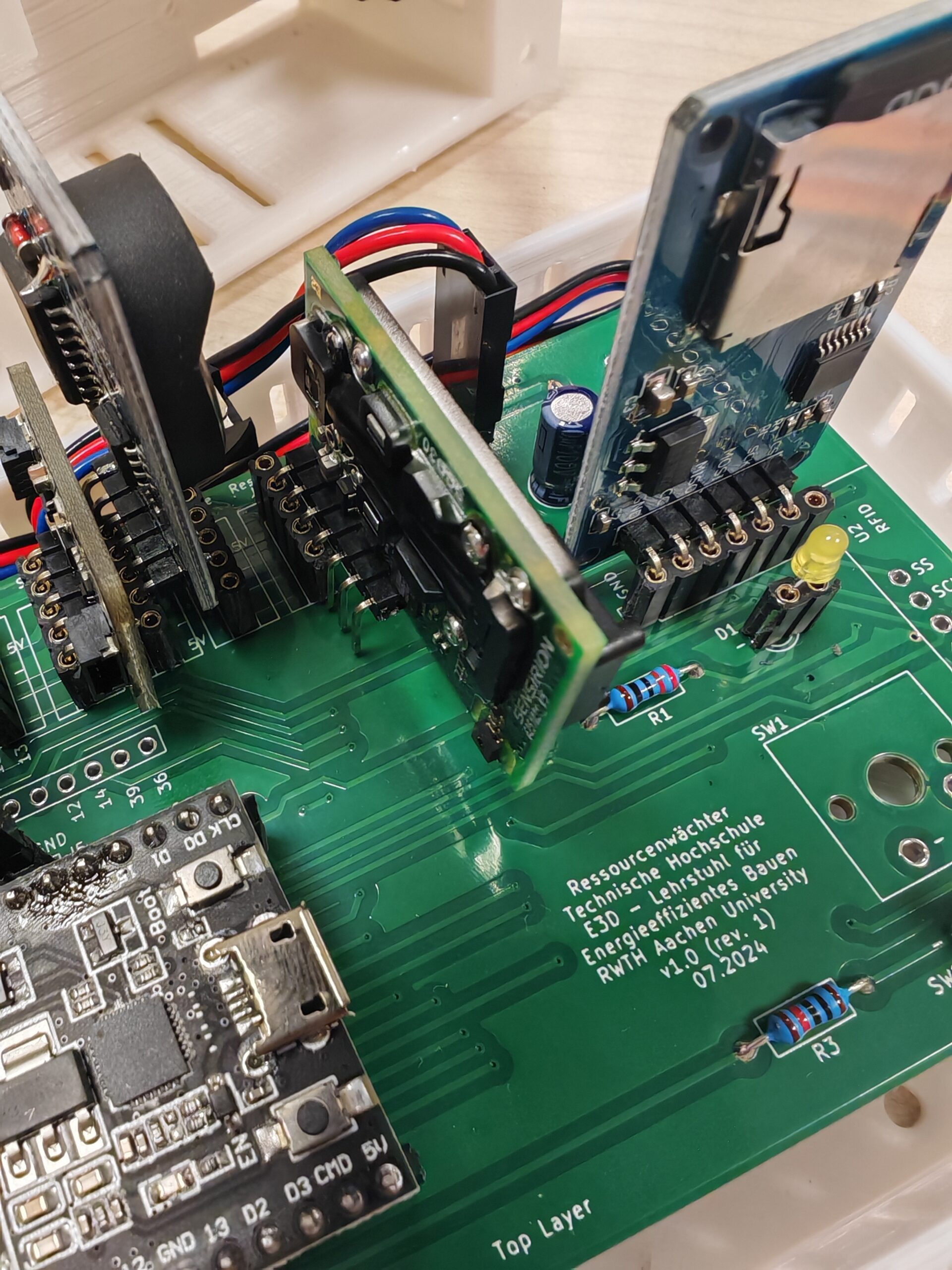
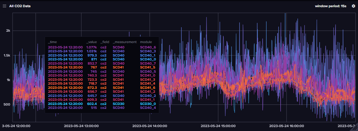
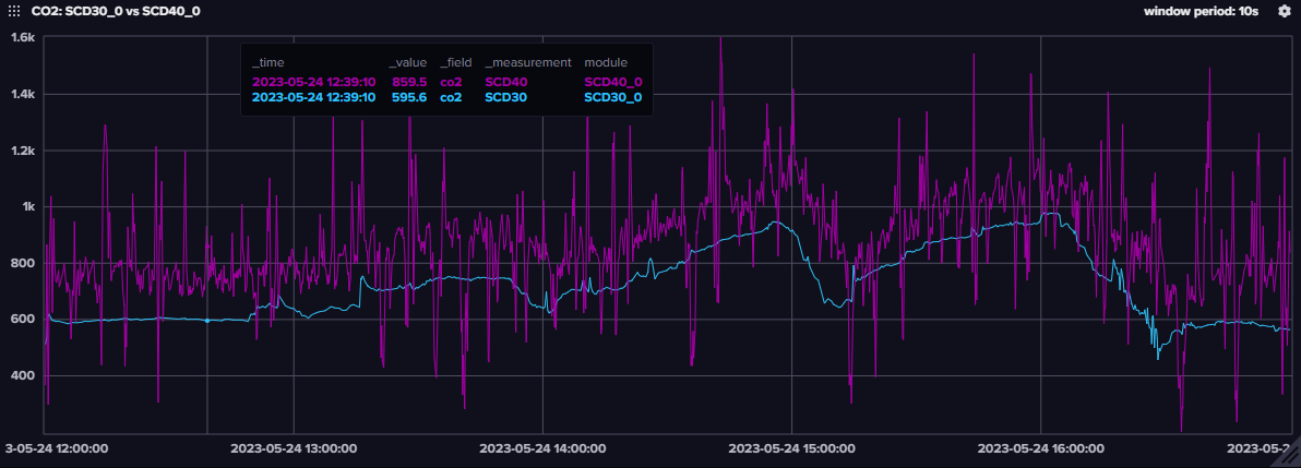
Sensirion also has another smaller CO2 sensor: the SCD40/41, which uses a different detection principle (photoacoustic NDIR) than the SCD30. However, our previous tests have shown that although this sensor is also accurate, it is inferior in terms of data stability (see below), perhaps because it does not have a dual channel as SCD30. If you use the SCD4x, we recommend using average sampling or moving averages to reduce data drift.
3.6 Wind Sensor Rev. C
Fix the wind speed sensor as shown in the figure below and connect it to the corresponding pin socket on the PCB using jumper wires.
Note: Due to the limited accuracy of low-cost wind speed sensors, we did not choose to use them in our field study after testing to avoid giving users a greater error in evaluating thermal comfort. More expensive anemometers (Wind Sensor Rev. P) from the same manufacturer performed better than Rev. C in our tests but were still imperfect (especially at low wind speeds). Both models required individual and laborious calibration. If you want to use Rev. P, you will also need to add a DC converter module to boost 5V to 12V (to power the Rev. P) and adjust the corresponding code in the Arduino sketch. For more details, please refer to the Modern Device tutorial.
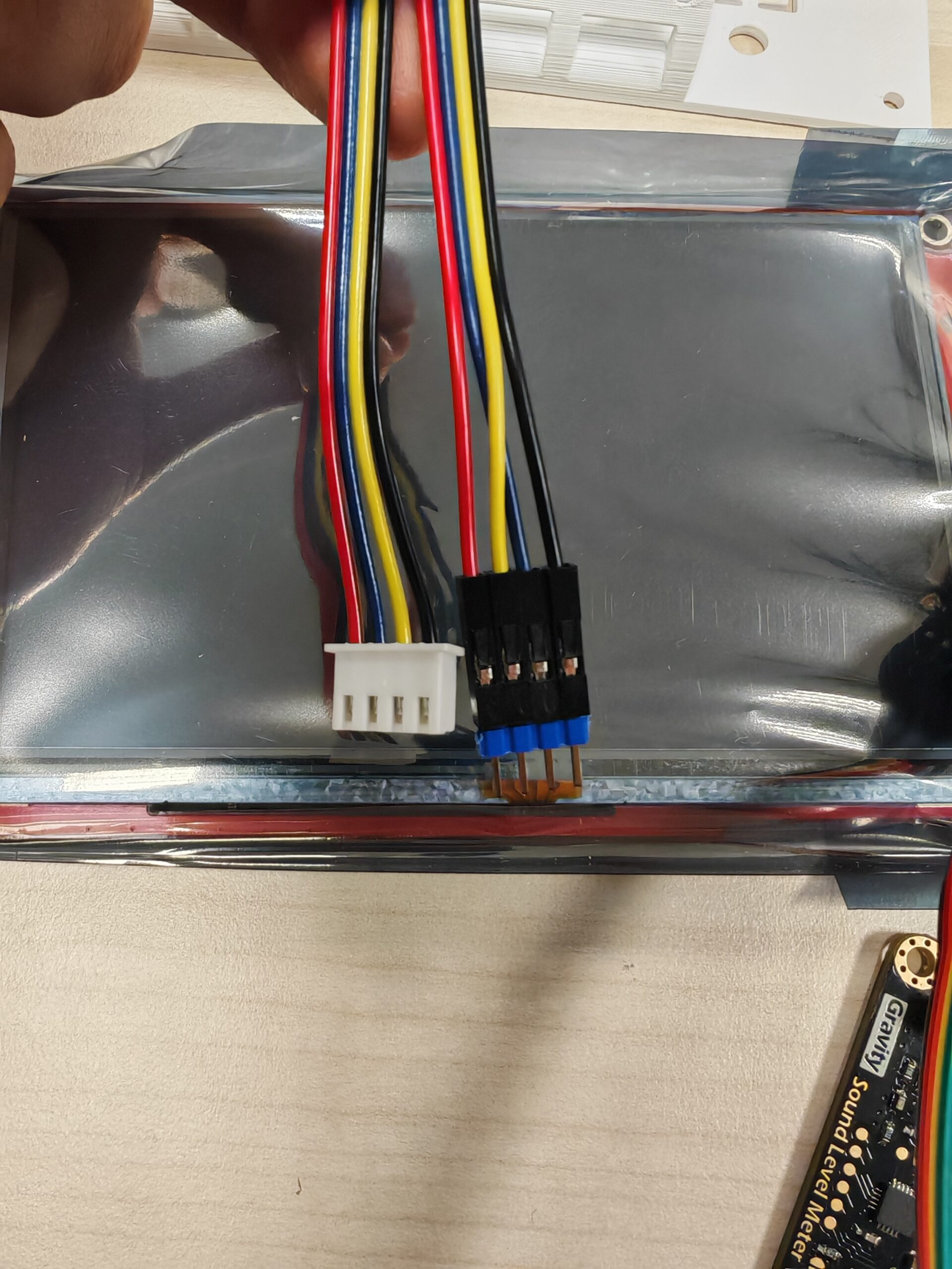
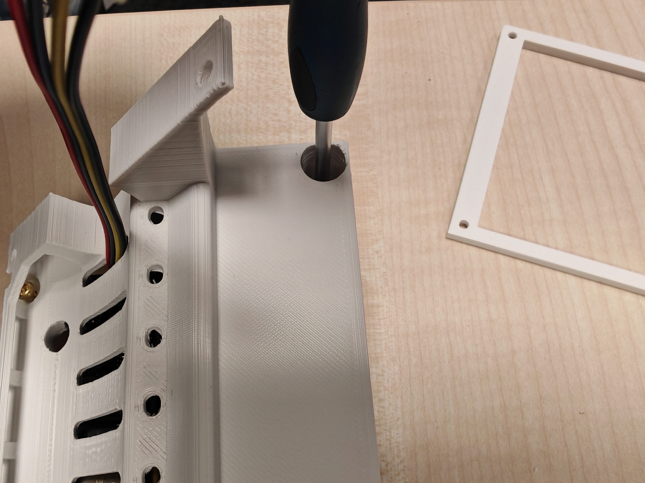
4. Connect to the touch display
Use the jumper wire included in the Nextion display packaging to connect the screen to the pin socket on the PCB through the hole in the enclosure. Note that you need to swap the jumper’s yellow and blue wires before connecting, as shown in the figure below. (Unfortunately, we forgot to swap RX and TX when designing the PCB…)

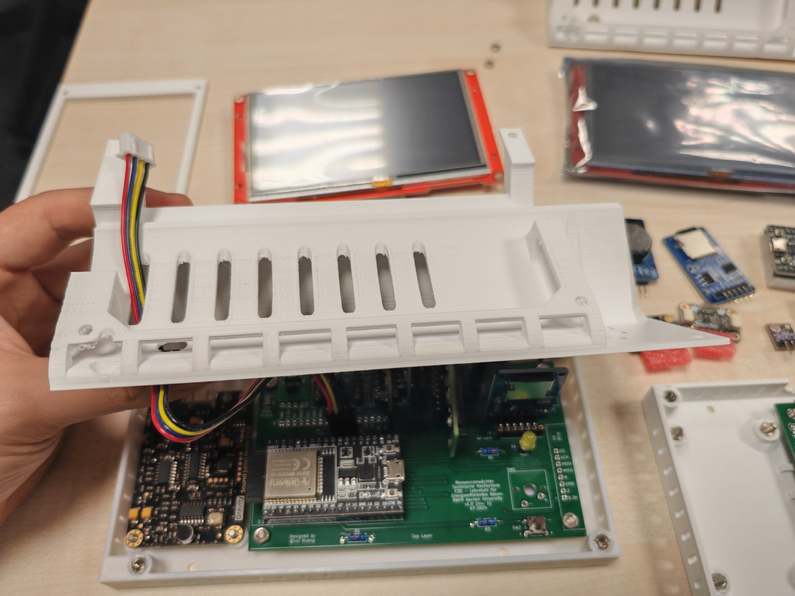
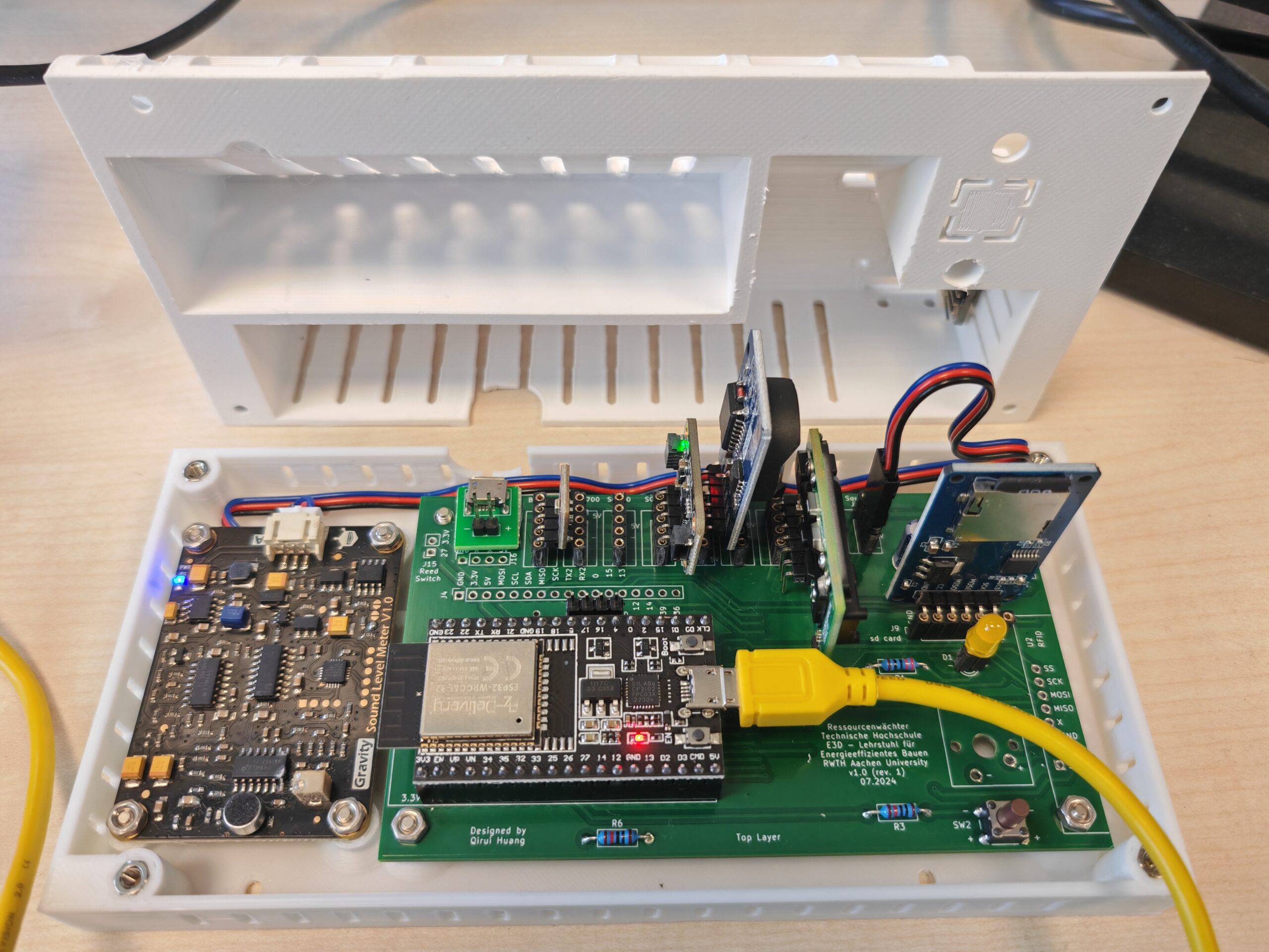
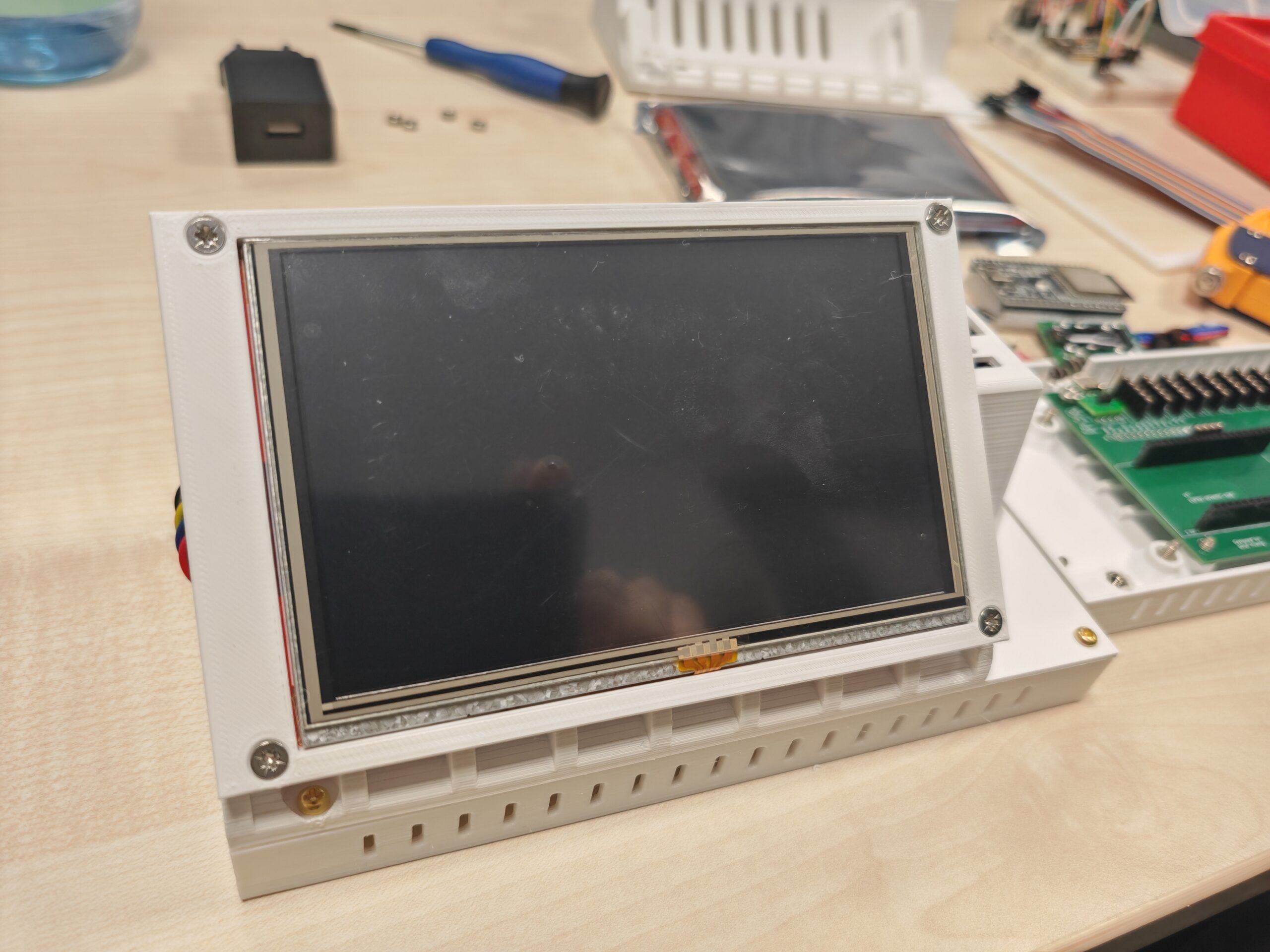
5. Final check & upload firmware
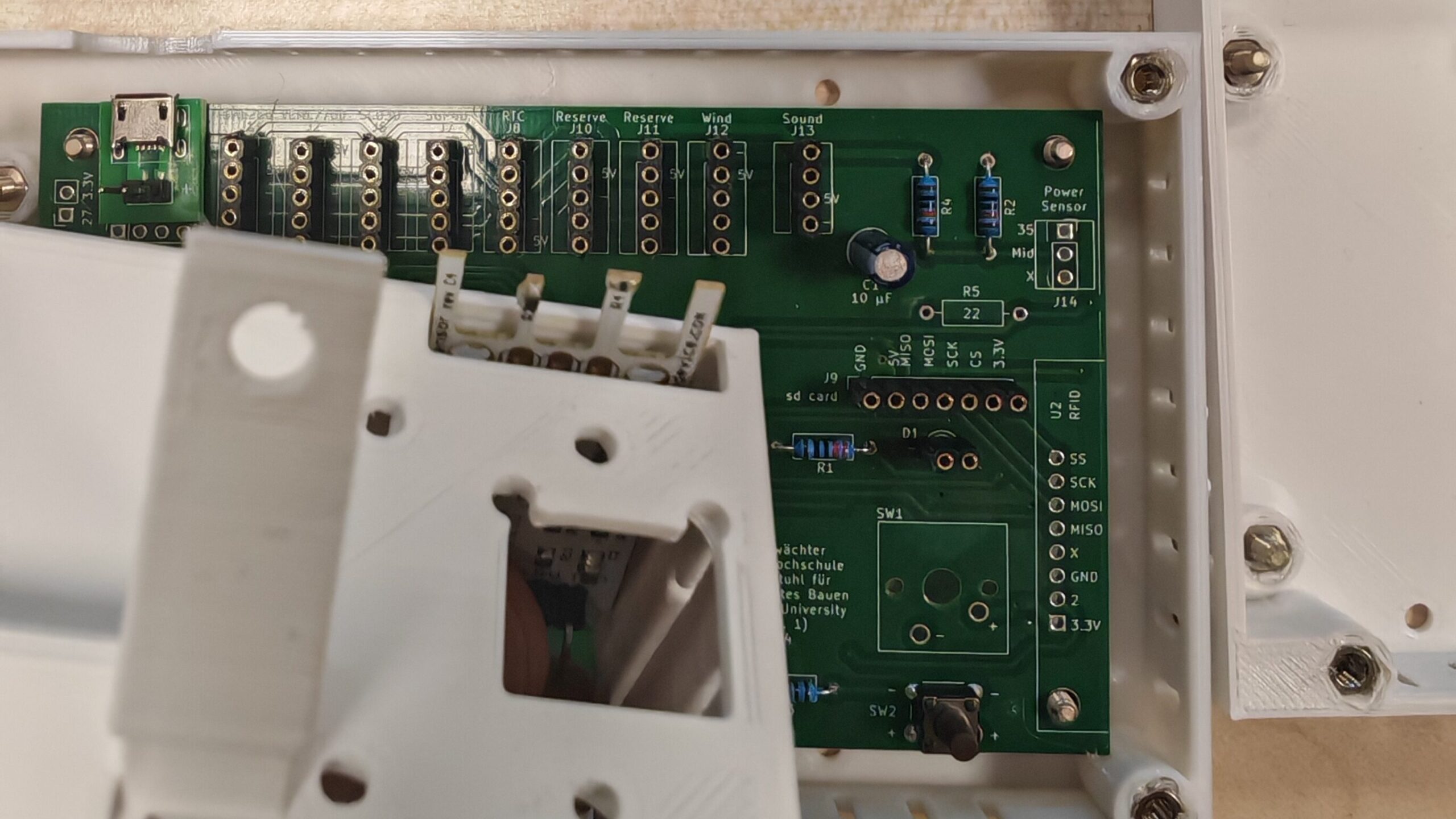
Check if all components have been correctly connected and if all jumper connections are secure. If you have followed our guide above (excluding Wind Sensor Rev. C), your Ressourcenwächter should look like this:
Connect the Microcontroller (ESP32) to the USB port of the computer using a Micro-USB cable. Note: Some USB docking stations may cause problems. If you encounter problems when using a USB docking station, such as the device not being detected, it is recommended that you connect directly to the USB port of the computer.
The microcontroller’s specific COM port can be viewed or modified in the device manager, or you can directly view the new COM port added after connecting to the ESP32 in the Arduino IDE. If you use a microcontroller for the first time, your computer may not have a driver for the CP210x chips. You can view this tutorial to follow the required serial port driver.
Follow the steps below to use the Arduino IDE to upload the firmware to the ESP32. If you are familiar with this, you can skip this part.
- Download and install the Arduino IDE.
- After installation, double-click to open the
arduino_gui_TouchDisplay.inofile (located in folder./firmware/Arduino/arduino_gui_TouchDisplay, see our Github repo (https://github.com/RWTH-E3D/ressourcenwaechter)). - Install the ESP32 development boards in the Arduino IDE, see these two tutorials: ESPRESSIF Tutorial, RANDOM NERD Tutorial.
- Install the libraries documented in
requirements.txtfollowing this tutorial. - Uncomment
#define UPDATE_RTCon line 17 (to update the RTC by the first uploading). - Configure upload settings:
- Board: ESP32 Arduino – ESP32 Dev Module
- Upload Speed: It doesn’t matter. If you have problems uploading, try selecting a slower speed like 115200.
- Port: COMxx (you can find out the COM port of your ESP32 in the device manager, or just plug in and unplug to see which COM port appears).
- You can leave the other settings blank (using defaults). If you want to minimize the ESP32’s power consumption, you can choose a lower CPU frequency (e.g., 80MHz).
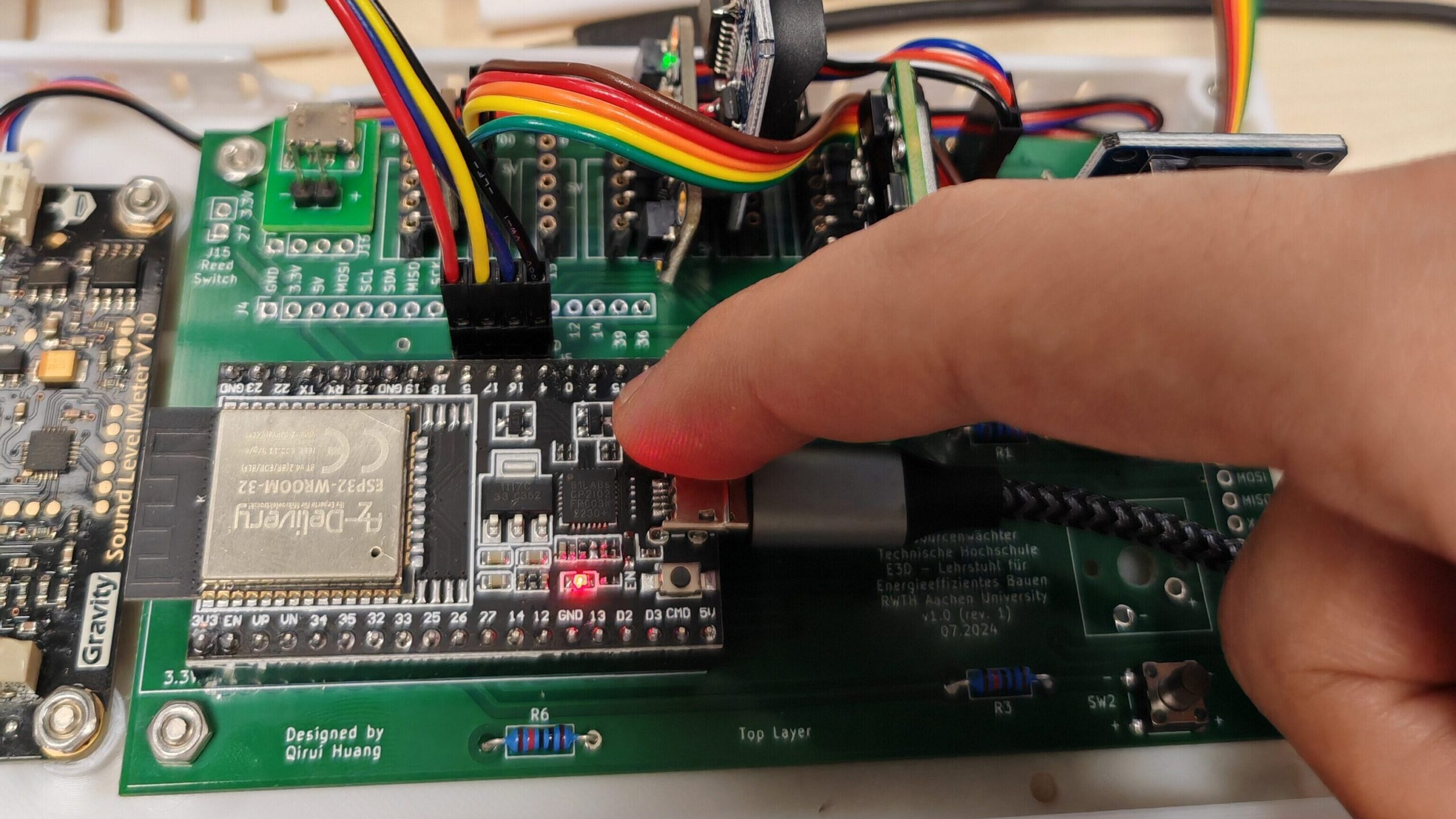
- Upload the firmware to ESP32. To do so, you must hold down the
Bootbutton on ESP32, as shown in the photo below. If you don’t know how to upload the firmware, please check this tutorial. - Comment
#define UPDATE_RTCon line 17 (to disable RTC update) ->//#define UPDATE_RTC - Upload the firmware to ESP32 again.
Note: If you use a different sensor configuration than the one described in this guide, please adjust the configuration in the module_cfg.h file. For details, please see Sensor Configurations.
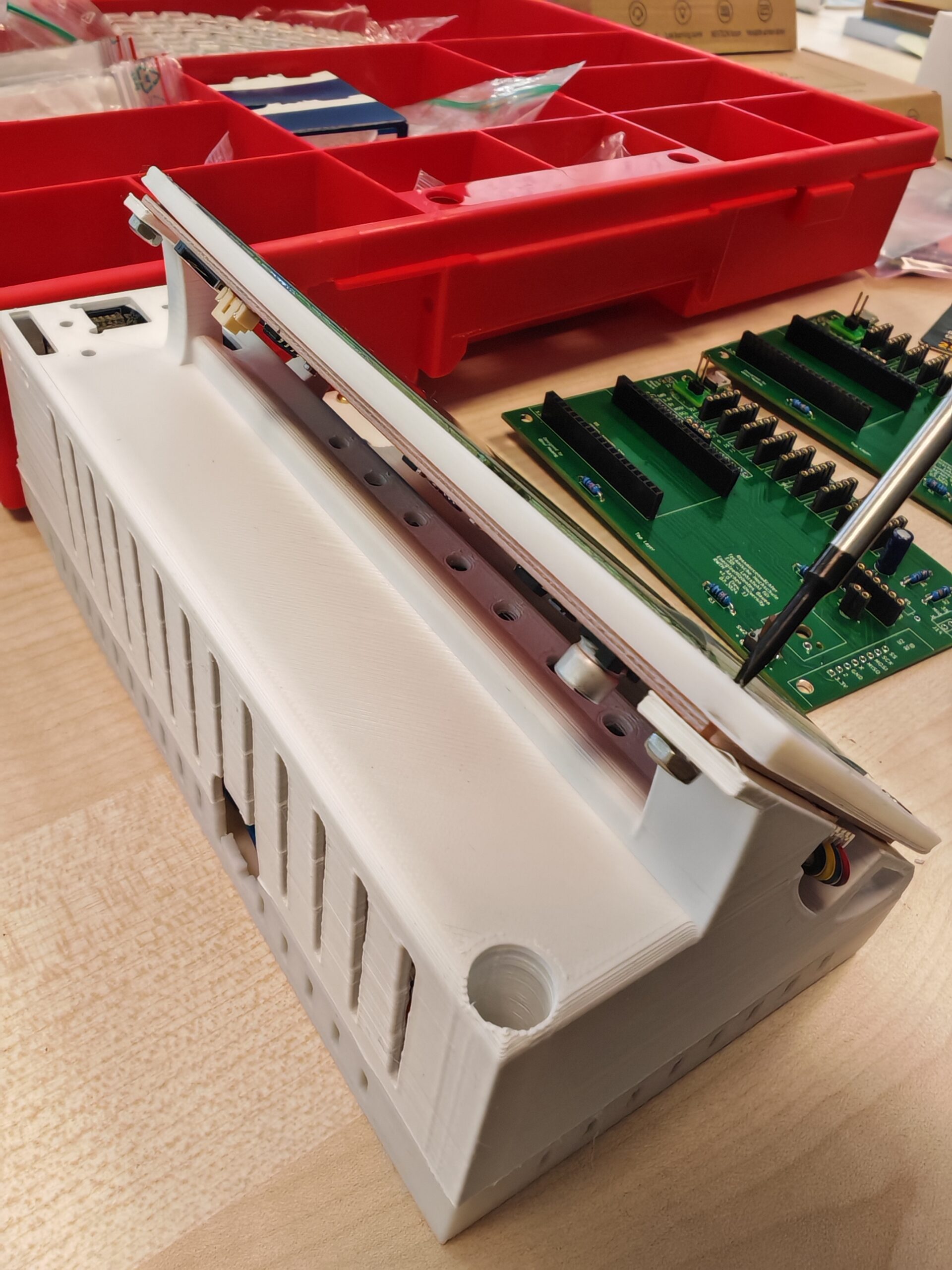
After the firmware has been uploaded, the enclosure can be assembled. Take care not to damage the jumper wires during assembly.
6. Upload display GUI
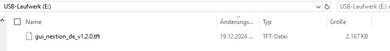
After assembly, prepare a FAT32-formatted micro SD card and copy the touch display GUI file (.tft format) to the SD card. Make sure that there is only one file on the card. See the example below (Nextion display, German version):
The different language versions of the GUI for the Nextion display can be found here: ./software/gui/Nextion_HMI
The .tft files for the TJC display can be found here: ./software/gui/TJC_USART_HMI
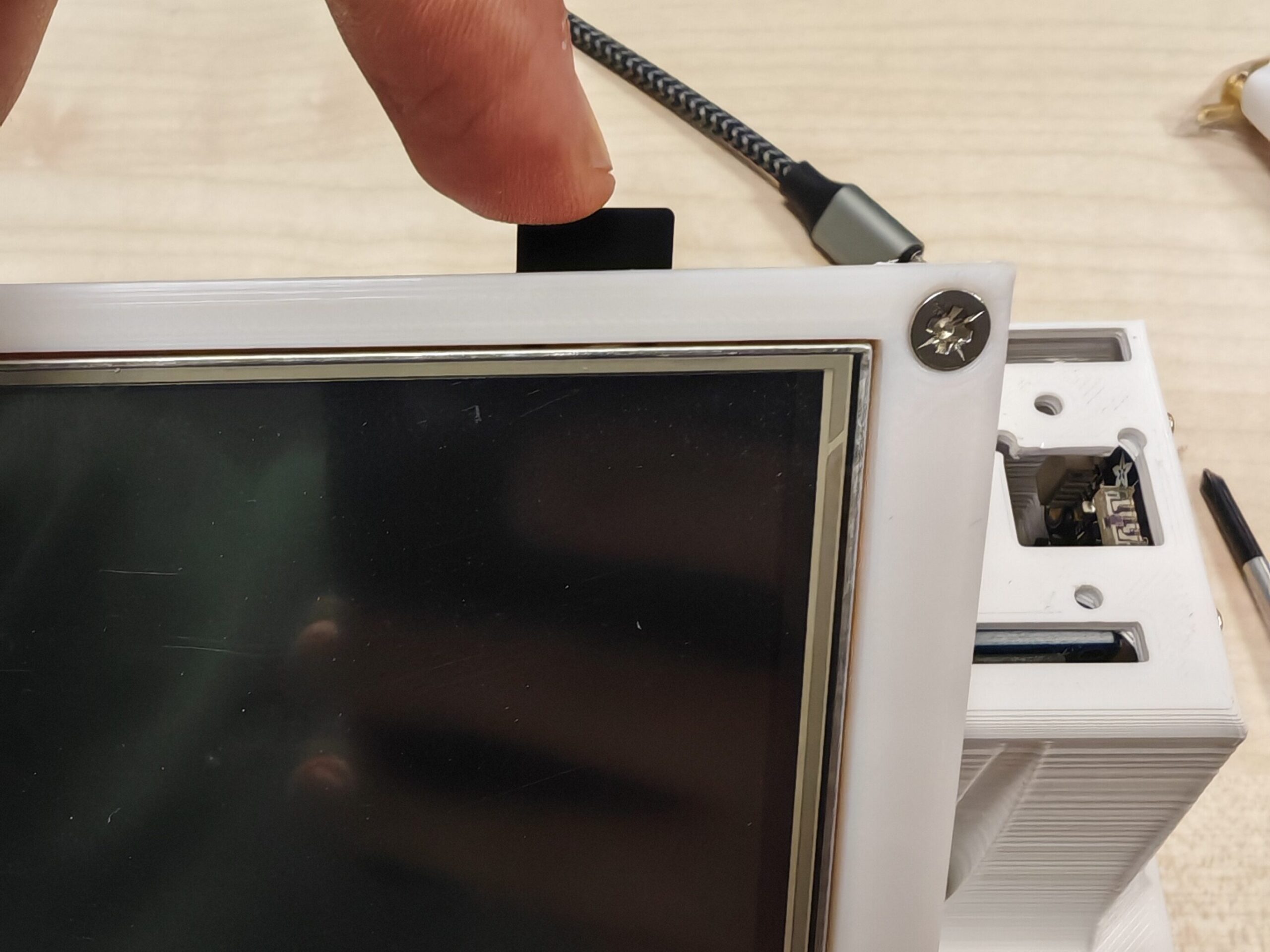
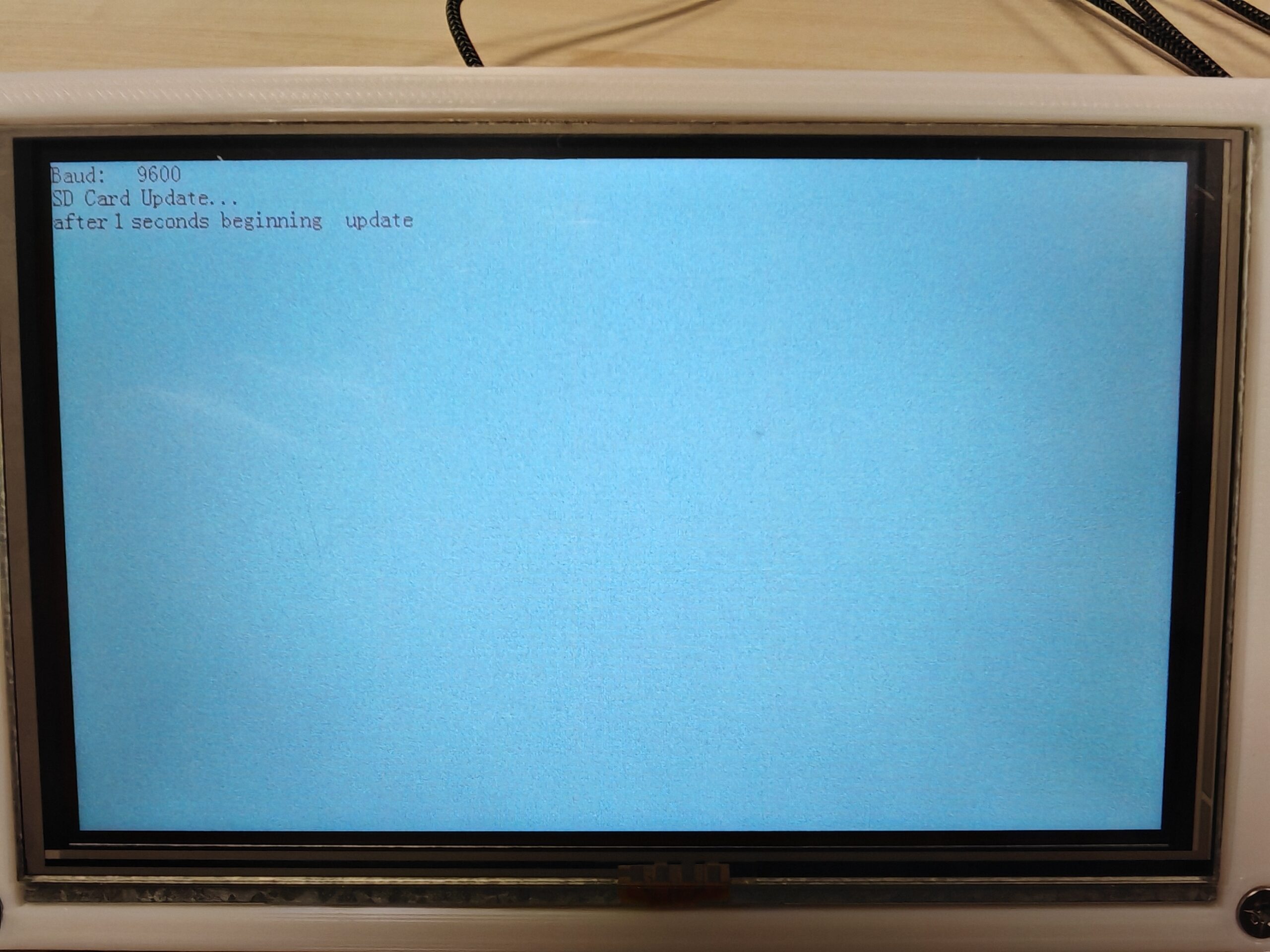
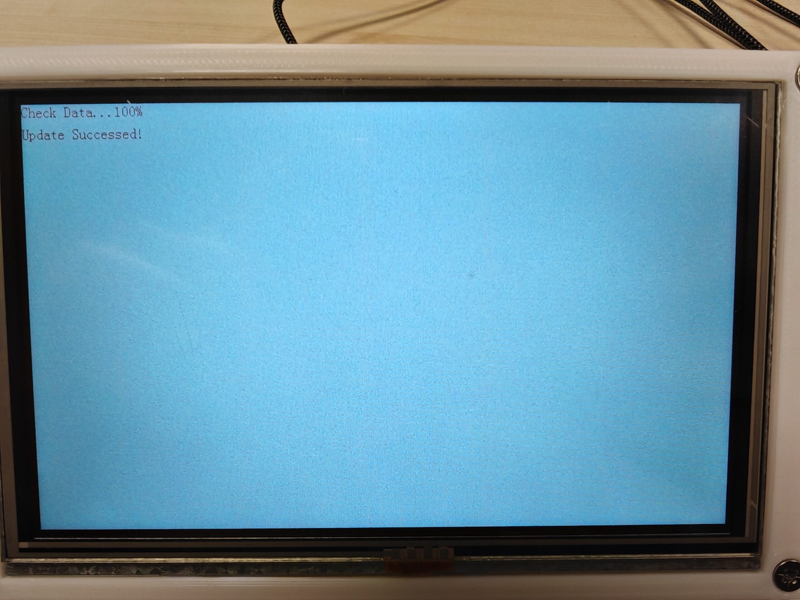
Now, insert the micro SD card into the slot on the back of the display while the device is switched off. Use a USB cable to power up Ressourcenwächter (with the USB port on the back of the device). After powering up, the display should show that the GUI is being updated, as shown below. Switch off the Ressourcenwächter after the GUI update (and when the LED is off).
After powering up again, the GUI should be displayed normally. Ressourcenwächter needs a short time to read the data on the micro SD card when it is first booted, and after the LED flashes a few times, all the data should be displayed.
7. Last steps
After uploading all the firmware, you can start using Ressourcenwächter!
To improve the monitoring quality and user experience, you can also perform the following steps:
- Calibrate the sensors, see Sensor Calibration for details. After calibration, adjust the corresponding parameters in the
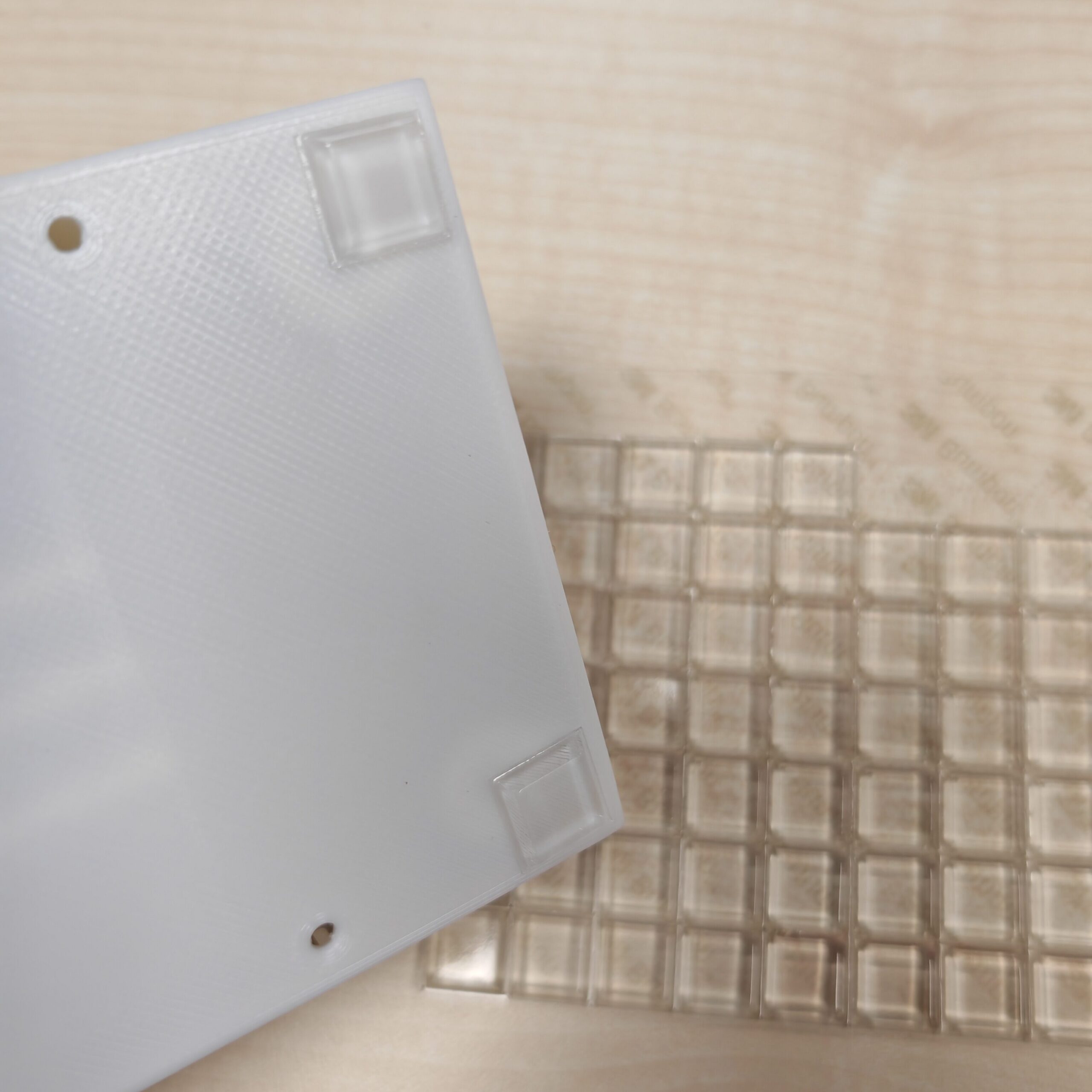
variables.hfile, open the housing, and re-upload the ESP32 firmware again. - Attach anti-slip pads to the bottom of Ressourcenwächter to prevent it from sliding backward when you tap the touch display.
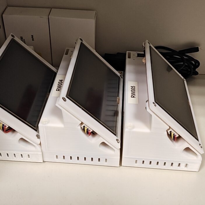
- If you have multiple Ressourcenwächters, don’t forget to number them!